Ring network implemented by telephony switches and links

a ring network and switch technology, applied in the field of telephony networks, can solve the problems of not having all the capabilities of a full-fledged separate data network typically needed, not expensive construction and provision of an additional network, and impracticality of tsc for networks comprising more than a few nodes, so as to save the processing of multiple message sending, simple method of adding, and the effect of increasing efficiency

Inactive Publication Date: 2005-01-04
AVAYA INC
View PDF8 Cites 11 Cited by
  • Summary
  • Abstract
  • Description
  • Claims
  • Application Information

AI Technical Summary

Benefits of technology

With this platform, PBXs can send data to specific PBXs in the network or broadcast the data to all other PBXs in the network without having to know the identity of each PBX or paths to take to make connections to the other PBX nodes. Only knowledge of the next PBX in the ring and the connection to the previous PBX and the next PBX is required. Prior art methods require separate data facilities that interconnect each of the PBXs and / or complex methods and databases to decide how to route the data from one location to the other or to each one using separate messages to each location which is to receive the data. That is, it is no longer necessary to maintain a pre-assigned database of which other PBX switches exist and how each can be addressed, and send the same message multiple times on numerous point-to-point connections.
The basic advantages of the invention are:1. Lower cost:a) It can use existing telephone networks,b) It uses existing PBX switch processor with added software,c) It requires no new hardware, andd) It requires no separate host LAN / data network.2. Increased speed: time sensitive data is shared quickly via broadcast capability (this is important for the sharing of current waiting times invention).3. Greater efficiency:a) The invention does not require pre-assigned data bases containing the identities and routing instructions to each of the PBXs that will share the data,b) The invention saves processing of multiple message sending to send a separate message to each PBX, andc) The invention provides a simple method of adding new PBXs to the network; only connections and configuration information at the next and previous PBXs at the point where the PBX is added need be changed.

Problems solved by technology

But the construction and provision of an additional network is expensive.
Nor are all of the capabilities of a full-fledged separate data network typically needed.
Both of these characteristics make the TSC impractical for networks comprising more than a few nodes.

Method used


Image

  • Ring network implemented by telephony switches and links
  • Ring network implemented by telephony switches and links
  • Ring network implemented by telephony switches and links

Examples


Embodiment Construction

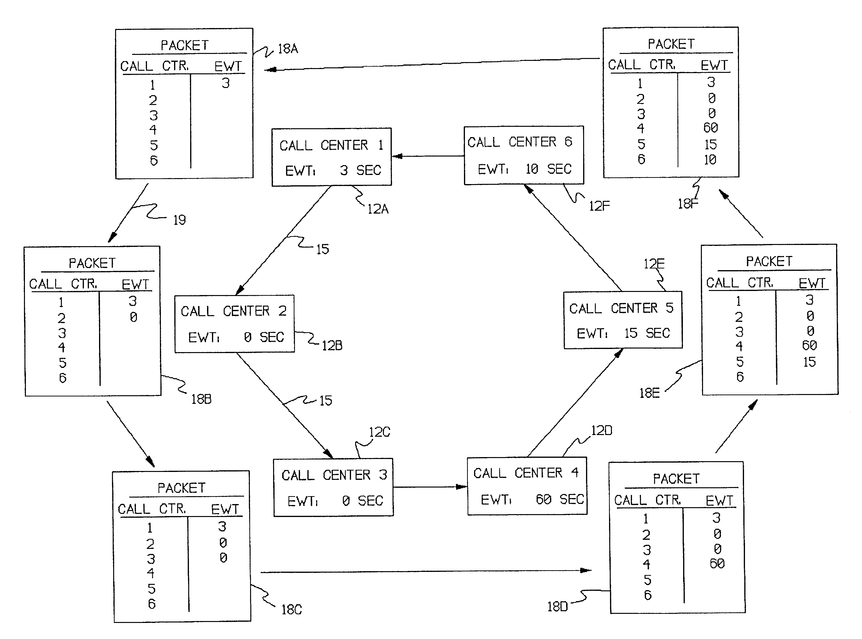
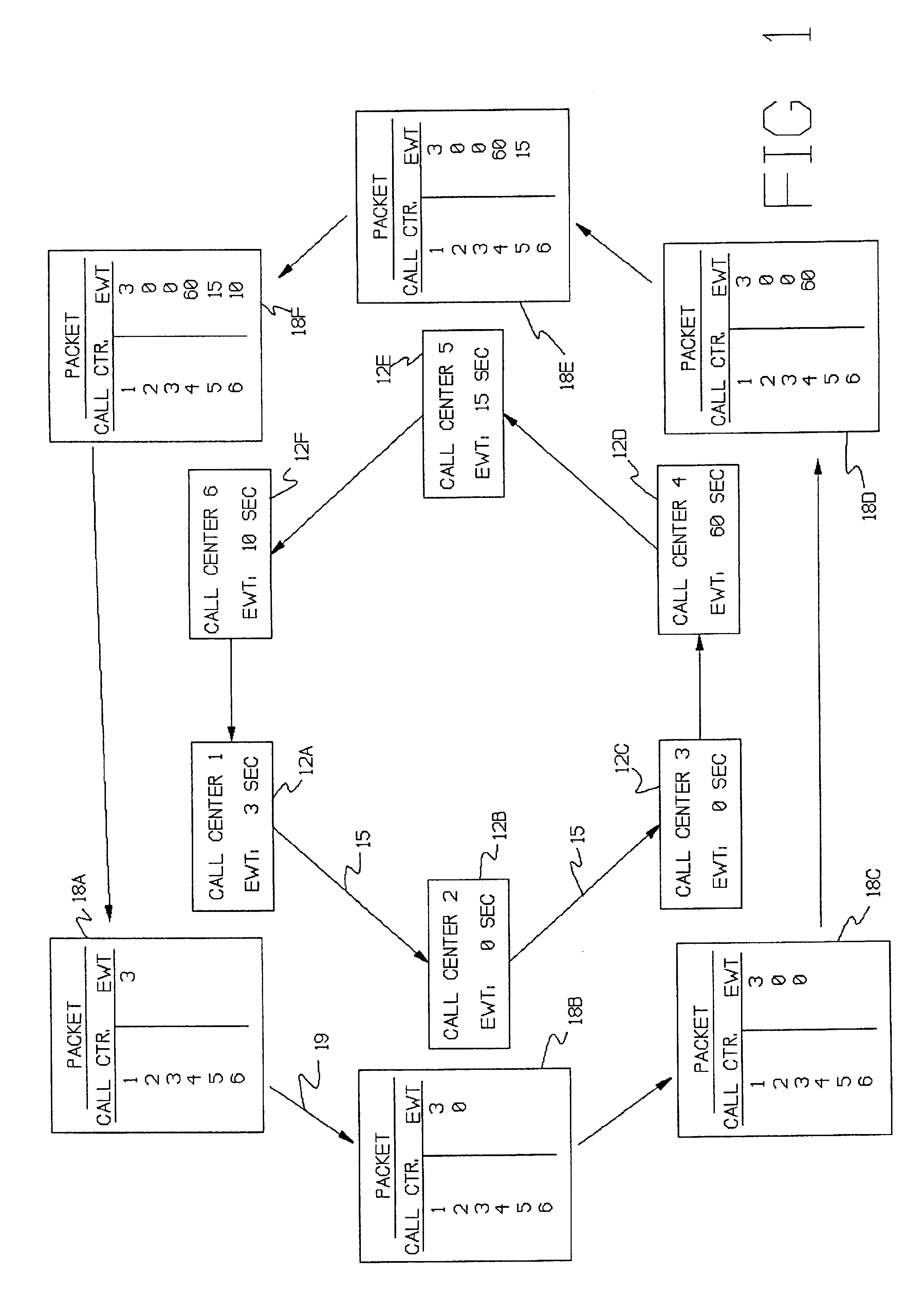
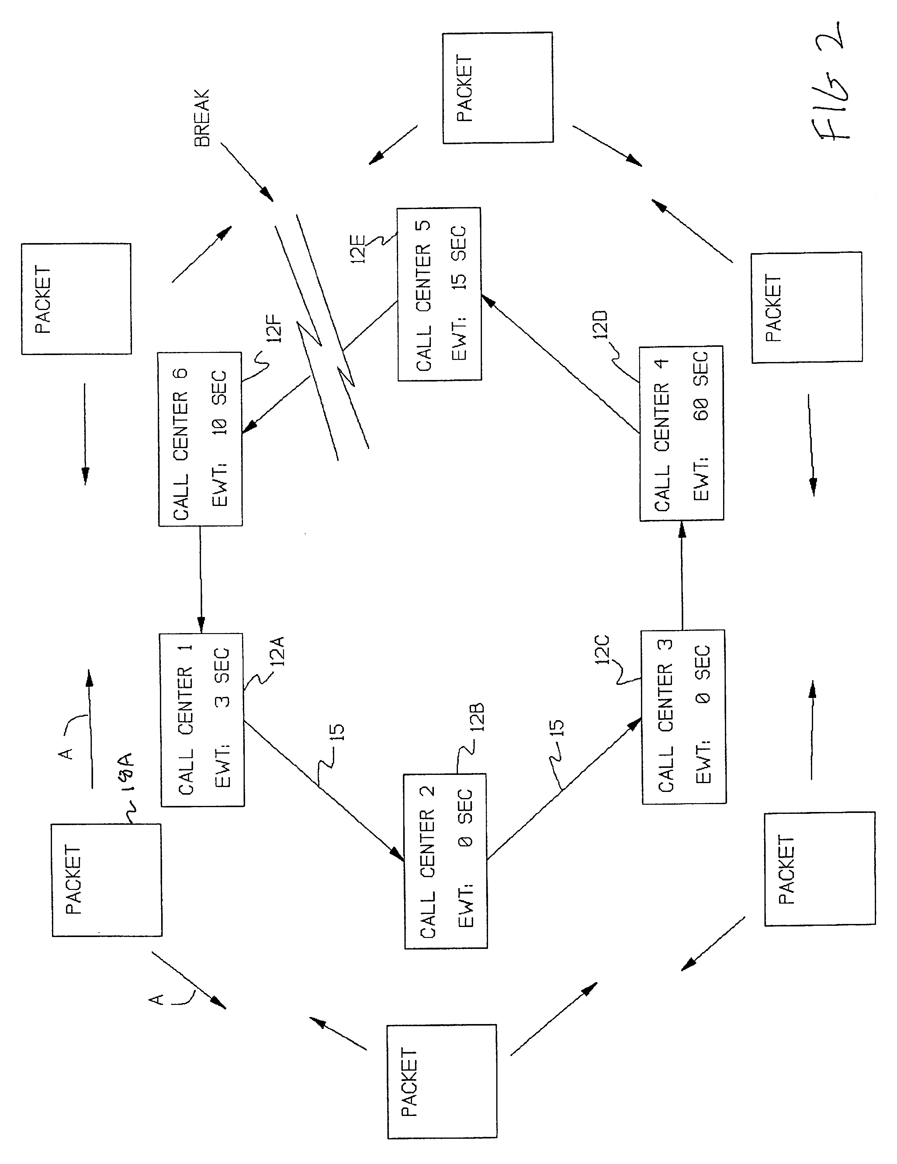
An example of use of this concept is in a multi-site call center network to provide intelligent and quick method for re-routing (interflowing) calls from a busier call center to one that is less busy (referred to as Network ACD). The idea in this example is for each call center to share its waiting time data among all other call center sites in the customer network using the method of the invention so that when a routing decision needs to be made, the data is already available and up-to-the-second and timely.

There is an inherent efficiency and economy of using a ring type of communication method where each call center does not need a connection to each other call center in a customer network and does not need to know ahead of time about the existence of the other call centers. Also, existing voice networks can be used without requiring addition of special data networks or added facilities or hardware.

Operation to share waiting time data among call center systems, or sites, or locati...


PUM


Abstract

A system for using an under-utilized data channel for carrying additional data, in a network mode. One such channel is the D-channel in the ISDN system. In one implementation, a group of telephone call centers share data, using the D-channel, about the lengths of time incoming callers must wait before being answered. Using the shared data, the call centers collectively route incoming calls to call centers having smaller waiting times.

Description

TECHNICAL FIELDThis invention relates to telephony networks and to the communication of control information in such networks.BACKGROUND OF THE INVENTIONConventional telephone networks comprise a plurality of telephone switching systems interconnected by telephone links, principally trunks, and sometimes lines. The links carry telephony traffic (or calls) and traffic-related (or call-associated) signaling between the switching systems. The switching systems normally have no capability to communicate control information to each other, apart from the call-associated signaling.If it is desired to communicate additional control information between the switching systems, they must be interconnected by a data network. But the construction and provision of an additional network is expensive. Nor are all of the capabilities of a full-fledged separate data network typically needed. All that the switching systems usually require are the following three features:1) The ability, at all times, of...

Claims


Application Information

Patent Timeline
Patent Type & Authority Patents(United States)
IPC IPC(8): H04L12/433H04L12/427H04Q3/00H04M3/523H04M3/50H04M3/12H04M7/00
CPCH04L12/433H04M3/5237H04Q3/0025H04M7/009H04M3/12H04M3/5232H04M7/06H04M7/12H04M2207/08H04M3/5238
Inventor FLOCKHART, ANDREW DEREKNALBONE, ROBERT DANIELFISHER, THOMAS S.MATHEWS, EUGENE P.
Owner AVAYA INC
Why Eureka
Try Eureka