Optical signal varying devices, systems and methods

a technology of optical signal and optical transmission system, applied in the field of optical transmission system, devices, and methods, can solve the problems of high cost of electrical signal regeneration/amplification equipment, attenuation of some signals, signal loss or distortion, etc., and achieve high gain signal, high loss, and flexible system operation

Inactive Publication Date: 2005-01-04
OPTIC153 LLC
View PDF54 Cites 11 Cited by
  • Summary
  • Abstract
  • Description
  • Claims
  • Application Information

AI Technical Summary

Benefits of technology

The design and length of the optical fiber used in conjunction with the pump source can be tailored to provide flexibility in operation of the system. For example, a concentrated, or lumped, high gain signal varying device can be provided using a small core fiber, such as dispersion compensated fiber. The lumped device further provides for a greater range over which the signal varying device can be used as

Problems solved by technology

Optical WDM systems were not initially deployed, in part, because high cost electrical signal regeneration/amplification equipment was required for each optical wavelength throughout the system.
However, EDFAs do not equally amplify each optical signal wavelength within the range.
The differences in amplification can result in attenuation of some signals and/or signal loss or distortion because of highly amplified noise.
As might be expected, restricting system designs to only those wavelengths that are comparably amplified by EDFAs severely limits the number of wavelengths and the information transmission capacity of WDM systems.
Thus, EDFAs generally must be operated with a limited power range to minimize amplification variations in the system.
The amplifier power limitations, in turn, increase the number of amplifiers in a system by limiting the a

Method used


Image

  • Optical signal varying devices, systems and methods
  • Optical signal varying devices, systems and methods
  • Optical signal varying devices, systems and methods

Examples


Embodiment Construction

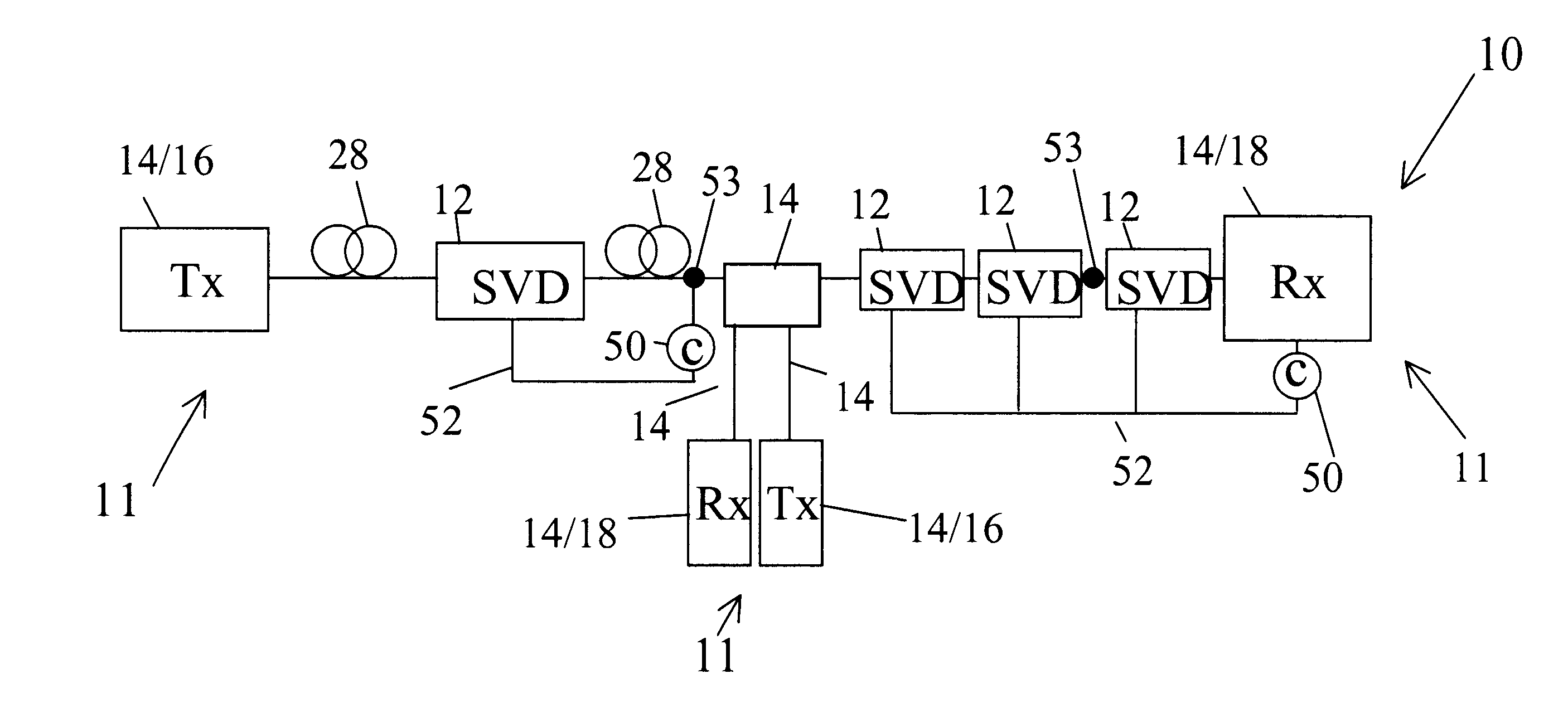
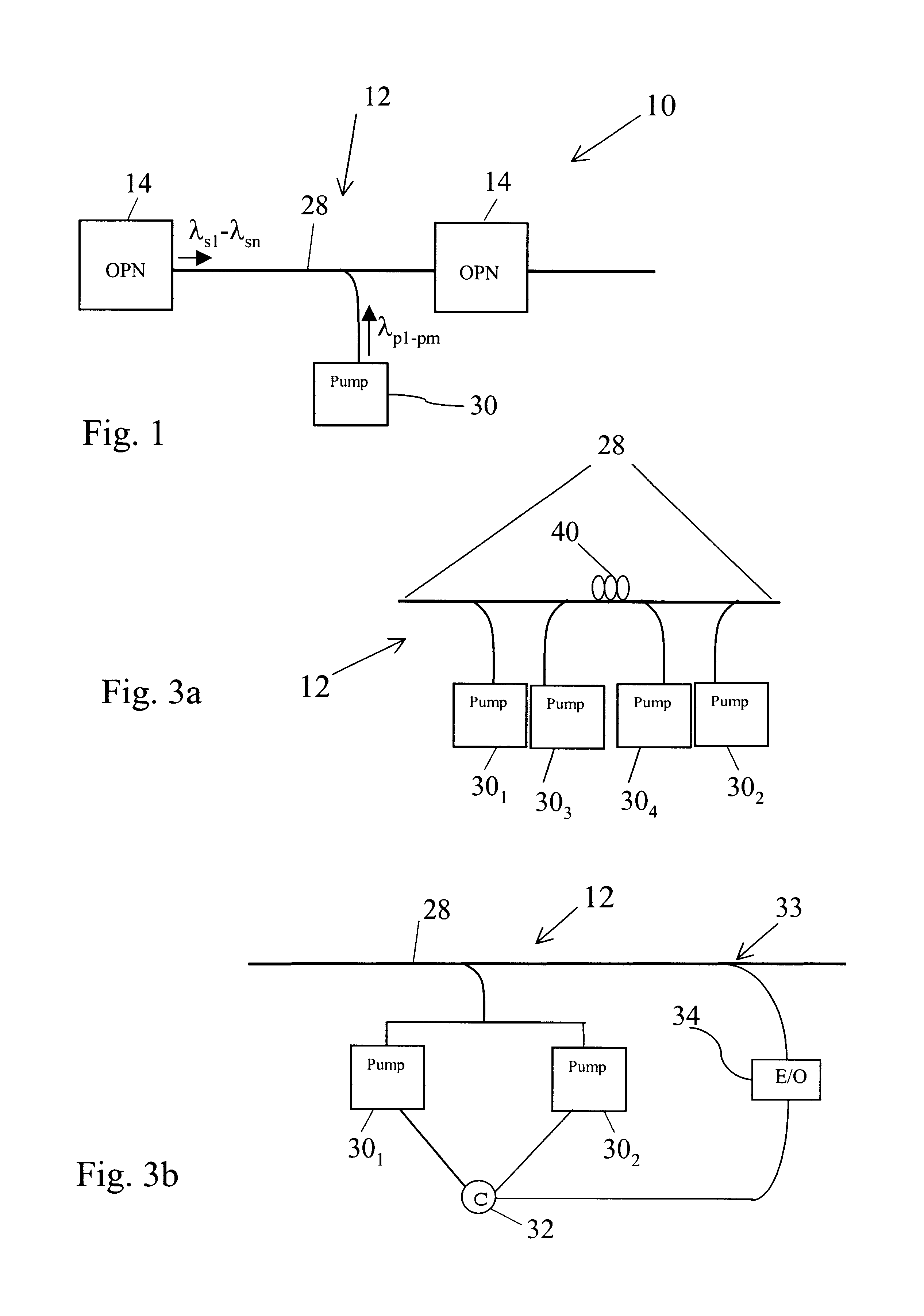
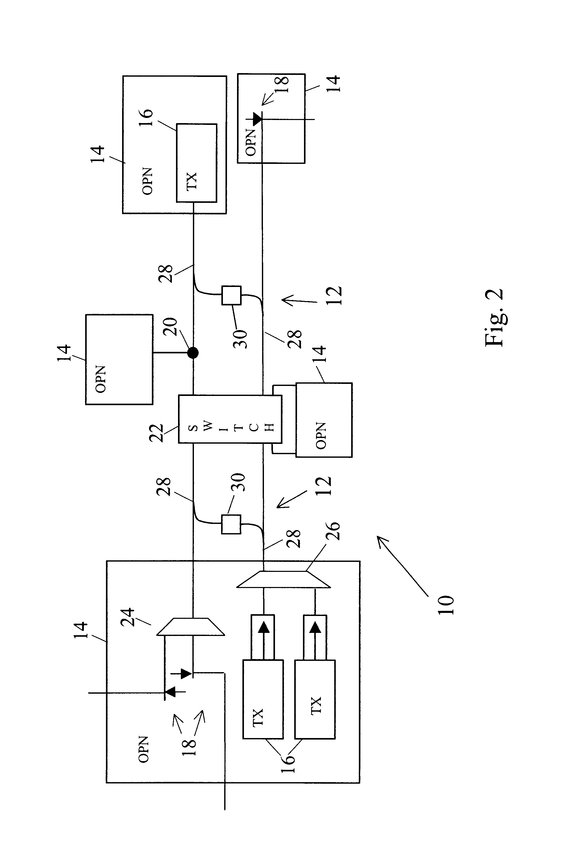
FIGS. 1 and 2 show embodiments of optical systems 10 in which signal varying devices 12 are optically connected between optical processing nodes 14. The system 10 can be embodied, for example, as one or more point to point links, as one or more rings, as a mesh architecture, or in one or more other system 10 architectures.

The optical processing nodes 14 can include one or more optical processing devices, such as transmitters 16, receivers 18, add and / or drop ports 20, switches 22, signal splitters 24 and combiners 26, or other signal processing devices. The optical processing nodes 14 generally include at least one transmitter 16 for transmitting optical signals in at least one information carrying wavelength to at least one optical signal receiver 18 located in another processing node 14. The transmitters 16 can include one or more light sources or emitters, such as lasers, incoherent sources, or other sources to provide optical channel power. Likewise, the receivers 18 can employ ...


PUM


Abstract

Optical systems, device, and methods including signal varying devices, such as optical amplifiers, attenuators, and filters that have controllable gain, loss and transparent intensity profiles, and which can include and be responsive to one or more local and remote controllers.

Description

STATEMENT REGARDING FEDERALLY SPONSORED RESEARCH OR DEVELOPMENTNot Applicable.FIELD OF THE INVENTIONThe present invention is directed generally to optical transmission systems, devices, and methods that provide for controllably varying characteristics of optical signals passing through the system. More particularly, the invention relates to optical systems, device, and methods including signal varying devices, such as optical amplifiers, attenuators, and filters that have controllable gain, loss and transparent intensity profiles, and which can include and be responsive to one or more local and remote controllers.BACKGROUND OF THE INVENTIONThe continued development of digital technology has provided electronic access to vast amounts of information. The increased access to information has fueled an increasing desire to quickly obtain and process the information. This desire has, in turn, driven demand for faster and higher capacity electronic information processing equipment (compute...

Claims


Application Information

Patent Timeline
IPC IPC(8): H04B10/17H01S3/30H01S3/094H01S3/102
CPCH04B10/2935H01S3/302H01S3/094096H01S3/1022H04B2210/003
Inventor GRUBB, STEPHEN G.ZANONI, RAYMONDSTEPHENS, THOMAS D.
Owner OPTIC153 LLC
Why Eureka
Try Eureka