Heat exchanger

a heat exchanger and heat exchanger technology, applied in the field of heat exchangers, can solve the problems of prohibitively high cost of nickel alloy materials, which can fulfil both functions, and achieve the effect of reducing the length of sinuously wound tubes and facilitating their removal from the du

Inactive Publication Date: 2005-01-11
INNOGY
View PDF17 Cites 71 Cited by
  • Summary
  • Abstract
  • Description
  • Claims
  • Application Information

AI Technical Summary

Benefits of technology

For this reason, the present invention has the duct forming the second passage which is spaced from the pressure vessel and is also separated from the pressure vessel by thermal insulation. Thus, the pressure vessel is protected from the high exhaust gas temperatures.
Preferably the tubes rest on ledges fixed to the walls of the duct such that the tubes are free to slide on the ledges. This allows for local thermal expansion of the tubes, and helps facilitate their removal from the duct

Problems solved by technology

Materials, such as nickel alloys, which can fulfil both functions are prohibitively expensive.

Method used


Image

  • Heat exchanger
  • Heat exchanger
  • Heat exchanger

Examples


Embodiment Construction

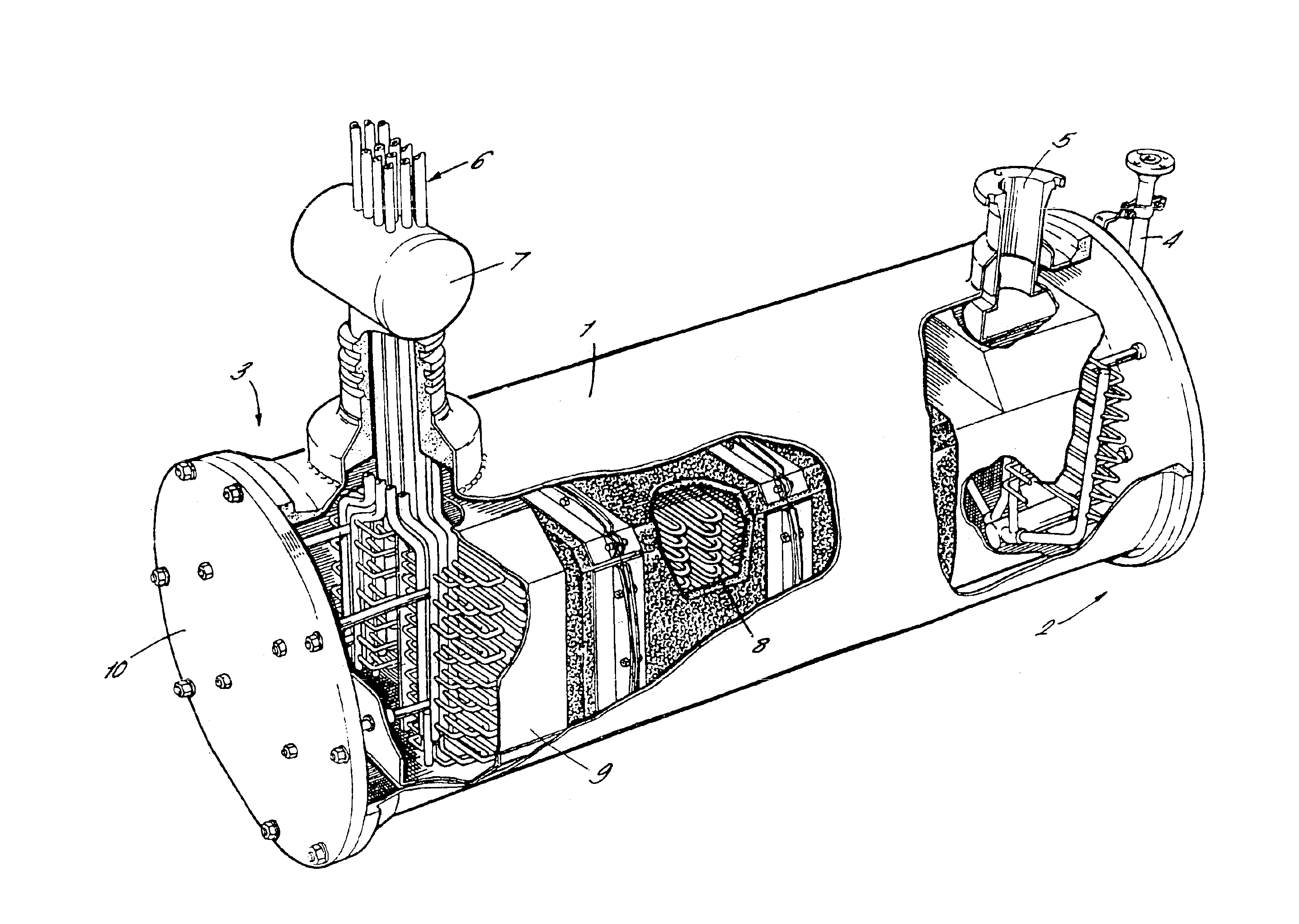
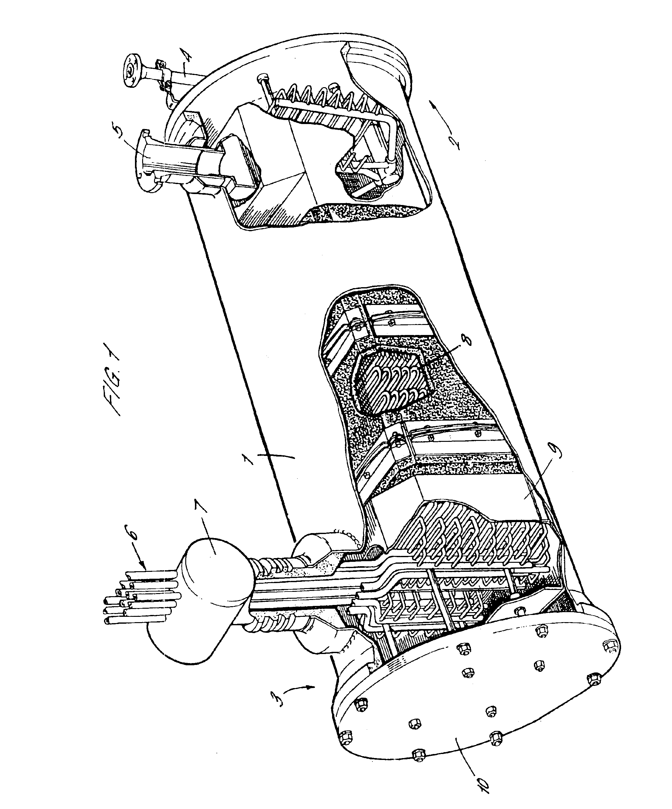
The heat exchanger described is a recuperator which is designed for use with an engine as disclosed in. FIG. 4 of WO 94 / 12785. The recuperator is designed to exchange heat between a cold flow of isothermally compressed air and a hot stream of expanded exhaust gas from a combustor. The heated compressed air leaving the recuperator is then fed to the combustor.

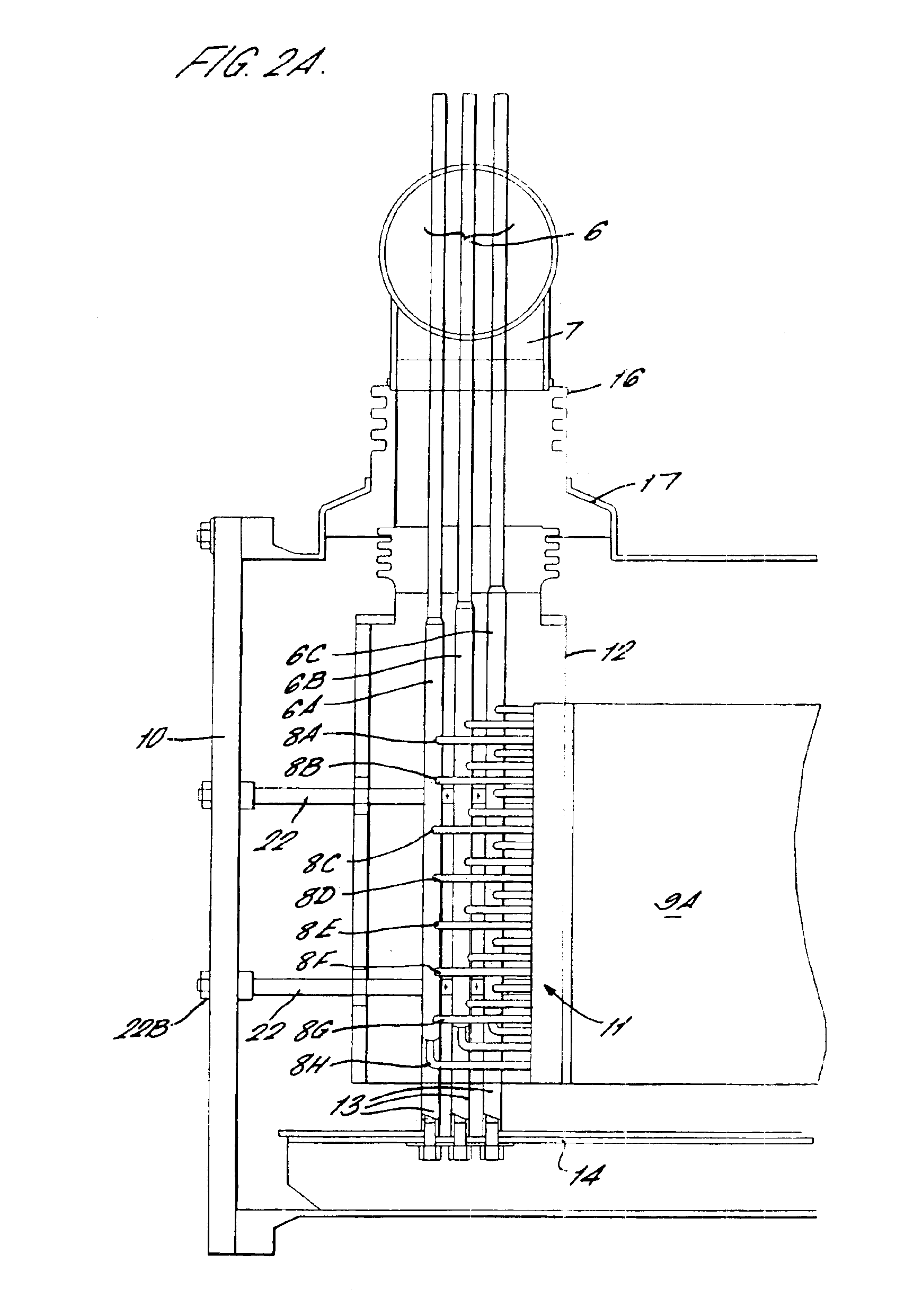
As shown, for example in FIG. 1, the recuperator comprises a pressure vessel 1 (e.g. of mild steel) inside which all other elements are housed. The recuperator has a cold end 2 and a hot end 3. A cold compressed air inlet 4 and a cold exhaust outlet 5 are provided at the cold end, while a hot compressed air outlet 6 and a hot exhaust inlet 7 are provided at the hot end. A plurality of serpentines 8 as described in detail below convey the compressed air from the cold end 2 to the hot end 3. A duct 9 having a substantially rectangular cross-section surrounds the serpentines 8 and conveys the exhaust gas from the hot end 3 to the c...


PUM


Abstract

A heat exchanger comprising a pressure vessel (1). A plurality of serpentines (8) convey a fluid to be heated through the pressure vessel (1) in one direction. A duct (9) surrounding the serpentines (8) conveys a second fluid in the opposite direction to give up its heat to the first fluid. The duct (9) is spaced from the pressure vessel (1) and is surrounded with thermal insulation (23). An opening in the duct (9) equalizes the pressure between the inside and the outside of the duct (9) which is also supported against expansion caused by the pressure inside the duct (9) exceeding the pressure outside the duct (9).

Description

BACKGROUND OF THE INVENTION(1) Field of the InventionThe present invention relates to a heat exchanger. The invention is applicable to any type of heat exchanger where heat from a first fluid stream is exchanged with heat from a second fluid stream.(2) Description of Related ArtThe invention has particular application to a recuperator which enables the hot gases leaving a high temperature source such as a furnace or gas turbine to heat the incoming air. Such a recuperator is used in the engine disclosed in FIG. 4 of WO 94 / 12785.In this engine, a countercurrent recuperator is used to preheat cold isothermally compressed air for use in a combustion chamber using expanded exhaust gas from the combustion chamber. This engine can be made to work using a conventional recuperator from gas turbine technology (such as the Solar Mercury 50). However, the pressure and temperature of the exhaust gas of the engine of WO 94 / 12785 can be greater than in a gas turbine. For example, the exhaust gas ...

Claims


Application Information

Patent Timeline
Patent Type & Authority Patents(United States)
IPC IPC(8): F28D7/08F28F9/00F28F9/013F28F9/007F28D7/00F02C7/08F01N5/02F28F1/00F28F13/12
CPCF28D7/08F28D7/085F28F9/00F28F9/013F28F2265/26F28F2270/00F28F2265/12F28F9/0275
Inventor WILSON, ALEXANDER BRUCECONEY, MICHAEL WILLOUGHBY ESSEXGOOCH, DAVID JOHNNATH, BIRENDRAPOWELL, ANDREW
Owner INNOGY
Why Eureka
Try Eureka