
Compact thermosiphon for dissipating heat generated by electronic components

a technology of electronic components and thermosiphons, which is applied in the direction of laminated elements, semiconductor/solid-state device details, lighting and heating apparatus, etc., can solve the problems of increasing the space required, requiring large package height, and disadvantageous assemblies for faster, smaller electronic devices, etc., and achieves the effect of adequate heat dissipation

Inactive Publication Date: 2005-01-11
COOLIT SYSTEMS INC
View PDF16 Cites 88 Cited by
  • Summary
  • Abstract
  • Description
  • Claims
  • Application Information

AI Technical Summary

Benefits of technology

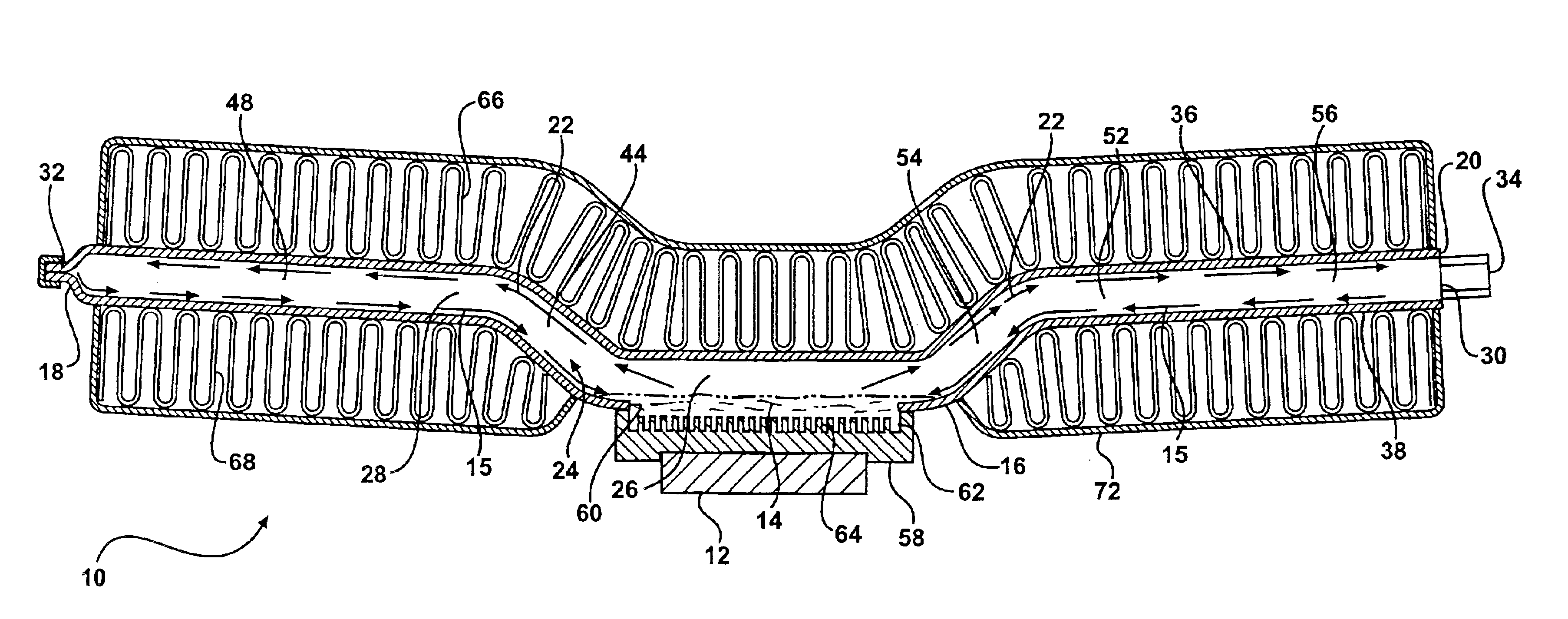
Accordingly, the subject invention overcomes the inadequacies that characterize the related art assemblies. Specifically, the subject invention provides a compact thermosiphon having a condensation region offset from an evaporation region. The location of the condensation region allows the thermosiphon to be compact and operate in smaller electronic devices while still providing adequate heat dissipation from the electronic components.

Problems solved by technology

However, they require additional space in the component for use in order to achieve maximum dissipation of heat because surface area is limited.
However, each of these related art assemblies require large package height for placing the thermosiphon in the electronic device because of their large condensation region.
Therefore, these assemblies are disadvantageous for use with faster, smaller electronic devices.
These external fins extend from both the evaporation region and the condensation region of the thermosiphons thereby requiring a substantial amount of space within the electronic device.
However, none of these thermosiphons have the condensation region offset from the evaporation region to allow for a compact thermosiphon design.

Method used


Image

  • Compact thermosiphon for dissipating heat generated by electronic components
  • Compact thermosiphon for dissipating heat generated by electronic components
  • Compact thermosiphon for dissipating heat generated by electronic components

Examples


Embodiment Construction

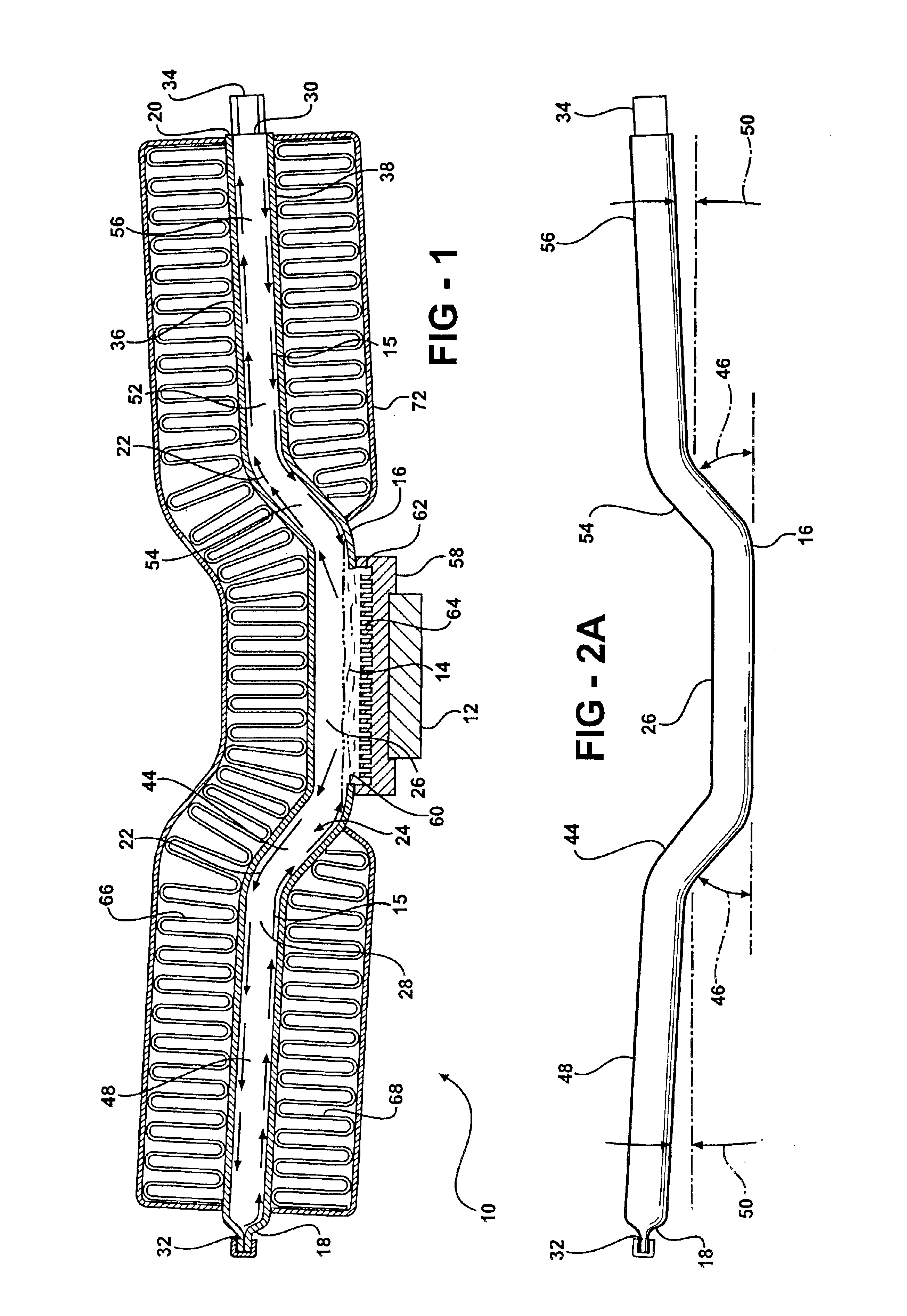
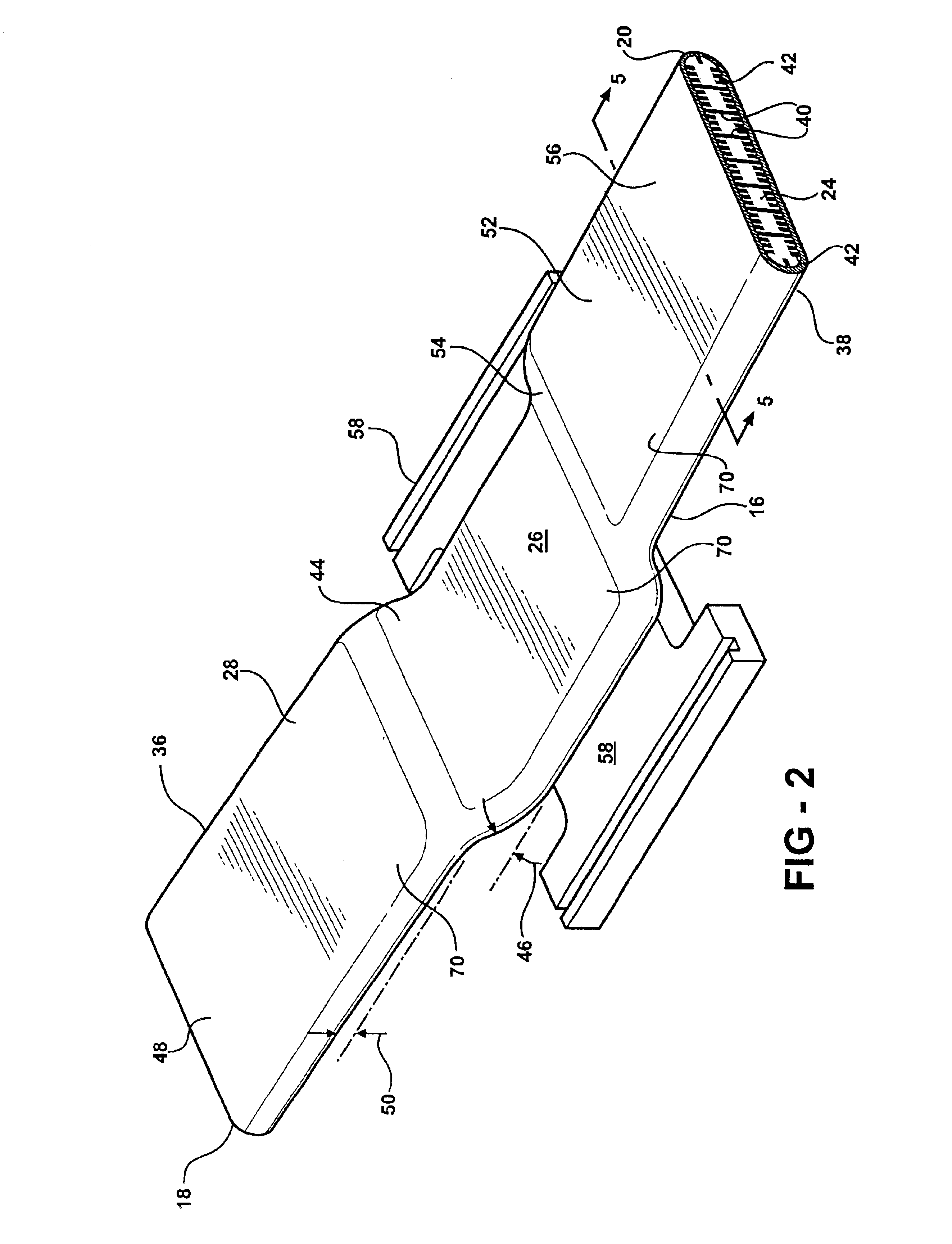
Referring to the Figures, wherein like numerals indicate like or corresponding parts throughout the several views, a compact thermosiphon assembly for dissipating heat generated by electronic components 12 using a working fluid 14 is shown generally at 10 in FIG. 1. The subject invention is particularly useful with electronic components 12 such as computer chips, telecommunication chips, microprocessors assemblies, and the like. These electronic components 12 are used in various electronic devices (not shown), such as computer systems, telecommunication systems, and the like. The subject invention is particularly useful with commonly termed “1U” or 1.75 inch package height computer server applications. The electronic components 12 are preferably flexibly attached to the thermosiphon assembly 10. However, one skilled in the art may connect the electronic components 12 by other methods without deviating from the subject invention.

Typical working fluids 14 that may be employed with the...


PUM


Abstract

A compact thermosiphon assembly for dissipating heat generated by electronic components using a working fluid includes a tube having a first end and a second end and a flat cross section defining an elongated chamber is disclosed. The tube has an evaporation region for receiving heat to evaporate the working fluid into a vaporized working fluid within the chamber disposed between a first condensation region and a second condensation region opposite the first condensation region for condensing the vaporized working fluid back into a liquefied working fluid within the chamber. Each of the condensation regions have a first portion extending upwardly at a first angle from the evaporation region and a second portion extending upwardly at a second angle different than the first angle.

Description

BACKGROUND OF THE INVENTION1. Field of the InventionThe subject invention relates to a compact thermosiphon assembly for dissipating heat generated by electronic components using a working fluid.2. Description of the Related ArtVarious thermosiphon assemblies for dissipating heat generated by electronic components using a working fluid are known to those skilled in the art. These assemblies typically include an evaporation region for receiving heat to evaporate the working fluid into a vaporized working fluid within the chamber and a condensation region for condensing the vaporized working fluid back into the liquefied working fluid within the chamber. External fins extend from the condensation regions into a cooling fluid, which is typically air, and the cooling fluid is forced past the external fins by another source, such as a fan.The evaporation region is directly below the condensation region which is directly below the external fins. The working fluid is vaporized in the evapo...

Claims


Application Information

Patent Timeline
IPC IPC(8): F28F1/40F28F3/00F28F1/02F28F1/10F28F3/02F28D15/02H01L23/427H01L23/34
CPCF28D15/0233F28D15/0266F28F1/022F28F1/40F28F3/025H01L23/427F28D2015/0216H01L2924/0002H01L2924/00
Inventor GHOSH, DEBASHISBHATTI, MOHINDER SINGHREYZIN, ILYA
Owner COOLIT SYSTEMS INC
Learn More