Friction stir welding method and structure body formed by friction stir welding

a technology of friction stir welding and friction stir, which is applied in the direction of manufacturing tools, transportation and packaging, other domestic objects, etc., can solve the problems of joint deformation and inability to produce satisfactory welds, and achieve the effect of short time and little deformation

Inactive Publication Date: 2005-01-11
HITACHI LTD
View PDF34 Cites 38 Cited by
  • Summary
  • Abstract
  • Description
  • Claims
  • Application Information

AI Technical Summary

Benefits of technology

It is a third object of this invention to enable two faces t

Problems solved by technology

Thus, when this welding method is applied to a two-face structure (panel), this downward force causes the joint mater

Method used


Image

  • Friction stir welding method and structure body formed by friction stir welding
  • Friction stir welding method and structure body formed by friction stir welding
  • Friction stir welding method and structure body formed by friction stir welding

Examples


Embodiment Construction

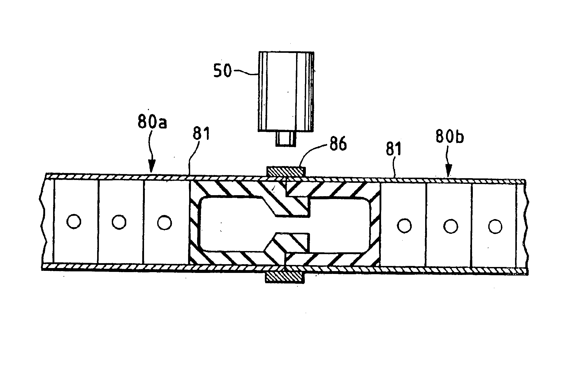
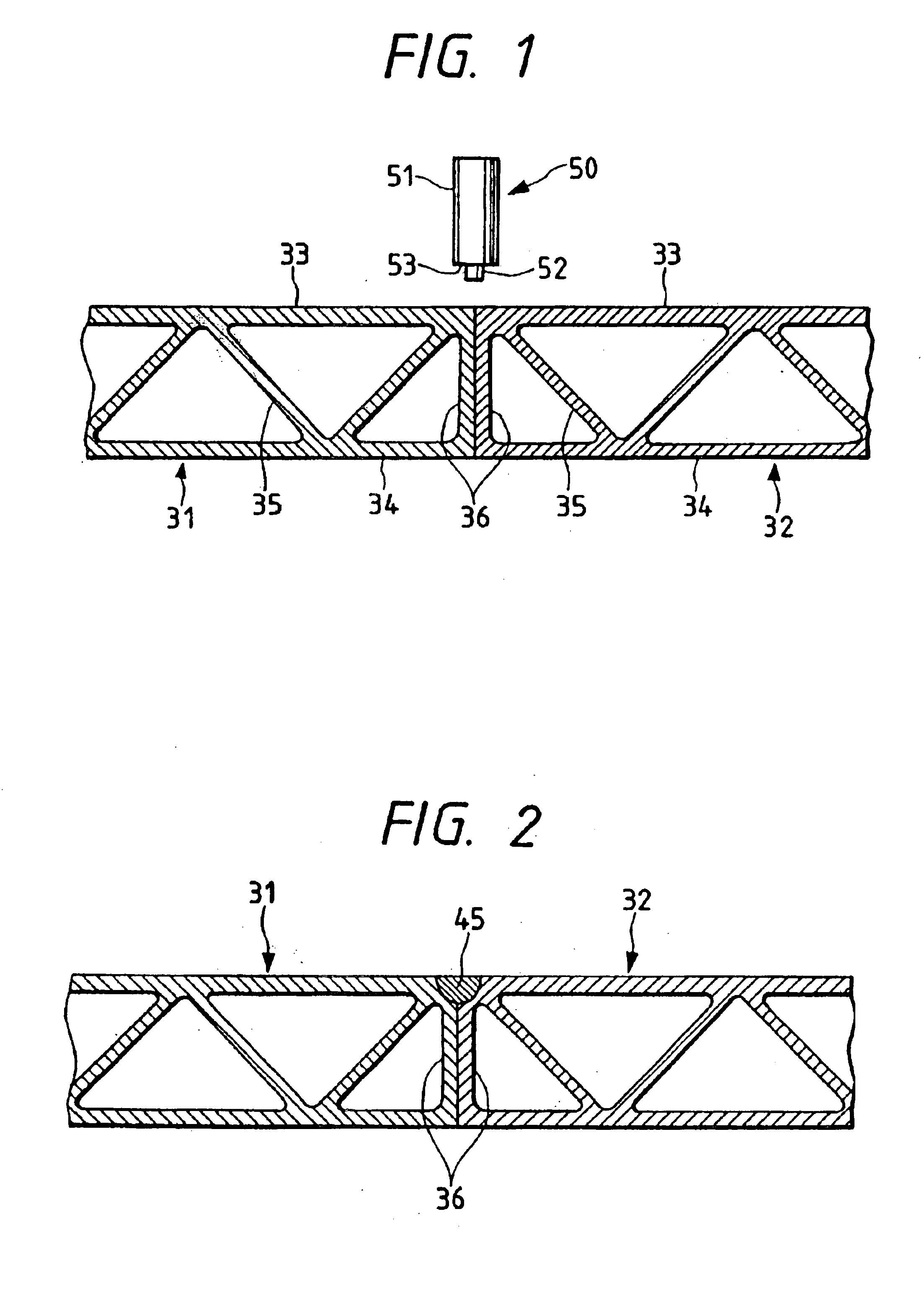
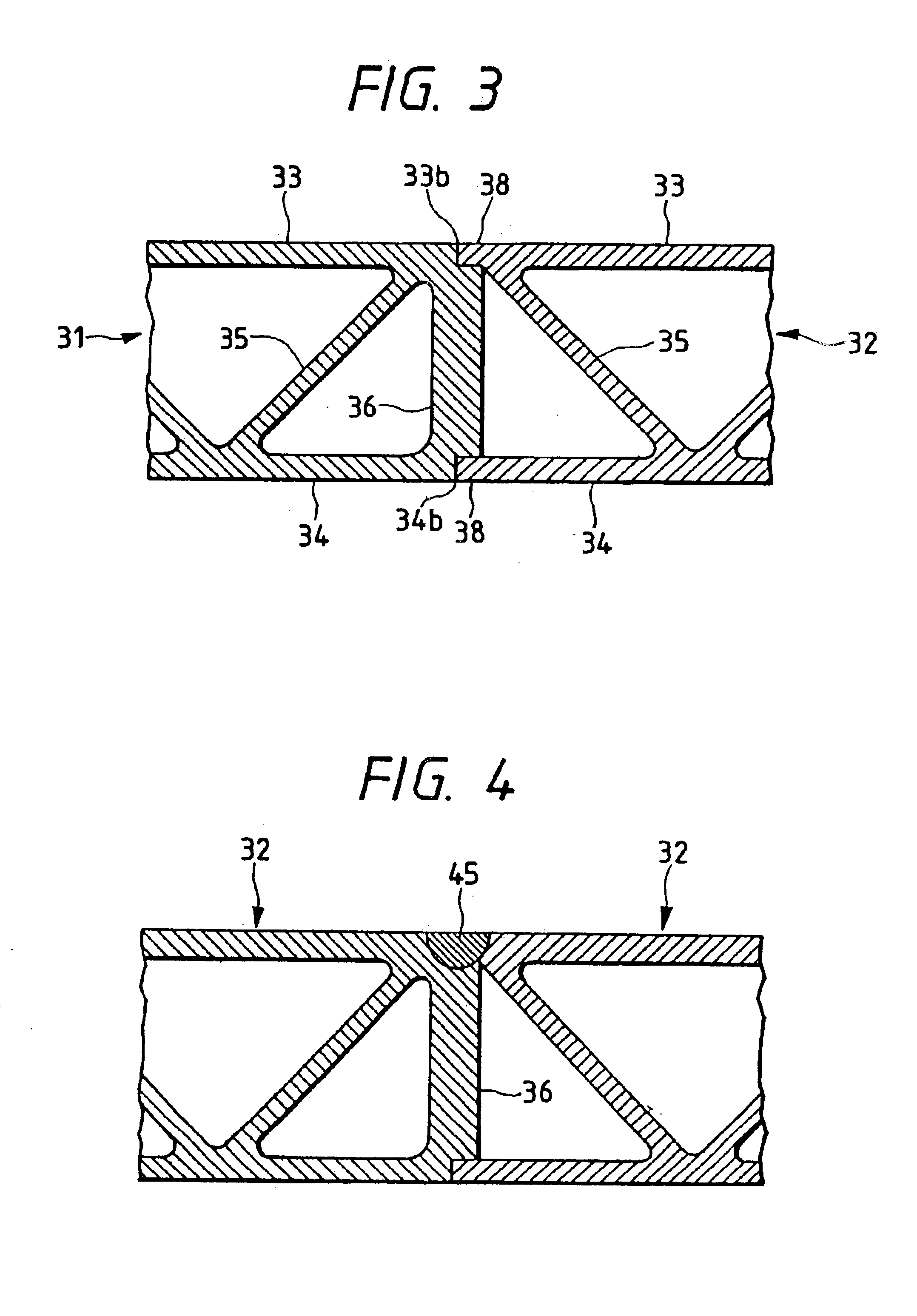
The embodiment shown in FIG. 1 has a joint configuration of the abutting type between hollow members 31, 32 which are in the form of panels. The hollow members 31, 32 have vertical plates 36, 36 at their ends in the width direction. Before the welding, the vertical plates 36, 36 are disposed immediately beneath a rotary tool 50. The vertical plates 36, 36 are opposed to and in contact with each other. If they are spaced apart, the distance is small and approximately 1 mm. On the extension of the interface between the vertical plates 36, 36 lies the center of a projection 52. The vertical plates 36, 36 have a stiffness which is sufficiently strong to sustain the downward force mentioned earlier. The vertical plates 36 are perpendicular to two plates 33, 34 in each panel. The hollow members 31, 32 are formed by extruding an aluminum alloy. The upper and lower faces of the hollow member 31 are flush with the corresponding upper and lower faces of the hollow member 32. That is, the holl...


PUM

PropertyMeasurementUnit
Thicknessaaaaaaaaaa

Abstract

This invention provides a configuration of a joint that allows a satisfactory welded joint to be formed with reduced deformation of the joint region when two-face structures (panels) are friction-welded end to end. The panels 31, 32 each have two substantially parallel plates 33, 34 and a third member 35 connecting the two plates 33, 34. The end portions of the plates 33, 34 of one panel 32 are friction-welded to the end portions of the plates 33, 34 of the other panel 32. At least one of the panels has a plate 36 at its end for connecting the plates 33 and 34 and has a rigidity to support a pressing force produced during the friction welding.

Description

BACKGROUND OF THE INVENTIONThe present invention relates to a friction stir welding method that is applicable to panel welding used, for example, in aluminum alloy railway cars and buildings.A two-face structure (panel) for railway cars using hollow members is disclosed in Japanese Patent Laid-Open No. 246863 / 1990, and another using laminated panels, such as honeycomb panels, is disclosed in Japanese Patent Laid-Open No. 106661 / 1994.The process of friction stir welding is performed by rotating a round rod inserted in a joint region to heat and plasticize the joint region thus forming a weld. This type of welding is generally applied to a butt joint and a lap joint, and is described in WO 93 / 10935 (which is the same as EP 0615480B1 and the Japanese Announcement laid-open publication No. Hei 7-505090 and in the publication Welding & Metal Fabrication, January 1995, pp. 13-16.SUMMARY OF THE INVENTIONIn friction stir welding, the reaction of the plasticized metal being extruded from imm...

Claims


Application Information

Patent Timeline
IPC IPC(8): B23K20/12B23K33/00B61D17/04E04C2/54B32B3/06B23K101/04B32B3/12F16B5/08F16B11/00
CPCB23K20/122B23K20/126B23K33/00B23K33/004B61D17/043E04C2/08E04C2/36E04C2/543B23K20/123Y10T428/24777B23K2201/045Y10T428/12Y10T428/12493Y10T428/1234Y10T403/478Y10T428/12375Y10T428/12382Y10T428/192B23K2101/045B23K20/12
Inventor AOTA, KINYATAKENAKA, TSUYOSHIISHIMARU, YASUO
Owner HITACHI LTD
Why Eureka
Try Eureka