Method of manufacturing sputter targets with internal cooling channels

a technology of internal cooling channel and sputter target, which is applied in the direction of manufacturing tools, forging/pressing/hammering apparatus, soldering apparatus, etc., can solve the problems of high sputtering rate bowing or bending, leakage, and sputtering impose considerable thermal energy on the sputter target assembly, so as to reduce bowing or bending, reduce electrical conductivity, and reduce the effect of thermal resistan

Inactive Publication Date: 2005-01-11
TOSOH SMD
View PDF24 Cites 48 Cited by
  • Summary
  • Abstract
  • Description
  • Claims
  • Application Information

AI Technical Summary

Benefits of technology

The bonding methods of the present invention allow target and backing plate assembly bonding with the assembly exhibiting reduced bowing or bending. Additionally, the low temperature pressure consolidation methods of the present invention do not cause undesirable grain growth of the target material or deformation of the cooling channels during consolidation of the target material with the backing plate material.
As a result, the sputter target assemblies in accordance with the present invention are able to utilize backing plate materials having higher thermal and lower electrical conductivity than the conventional backing plate materials normally compatible with a specific target material. The reduction of bowing and bending is especially beneficial in sputter target assemblies with internal cooling channels. The opportunity for leakage is greatly reduced by use of the low temperature pressure consolidation methods in accordance with the present invention.
A second objective of the present invention provides for formation of the cooling channels is such a way that the cooling channel formation also results in an interference friction fit bond between the target material and the backing plate material. Thereby, the time and steps necessary for sputter target assembly production are greatly reduced.

Problems solved by technology

Magnetron sputtering imposes considerable thermal energy upon the sputter target assembly, especially within the concentrated annular region of the target raceway.
These bonding methods typically involve imposition of high temperatures.
Sputter target assemblies bonded by these methods can bow or bend at high sputtering rates, especially when a large difference exists between the coefficients of thermal expansion for the target material and backing plate material.
In sputter target assemblies with internal cooling channels, bowing and bending induces leakage; the typical bonding methods, described above, tend to deform, or otherwise partially constrict, the cooling channels.
Additionally, known bonding techniques, as discussed above, result in undesirable grain growth in the target material or the resulting bond cannot withstand the stresses imposed by high sputtering rates.

Method used


Image

  • Method of manufacturing sputter targets with internal cooling channels
  • Method of manufacturing sputter targets with internal cooling channels
  • Method of manufacturing sputter targets with internal cooling channels

Examples


second embodiment

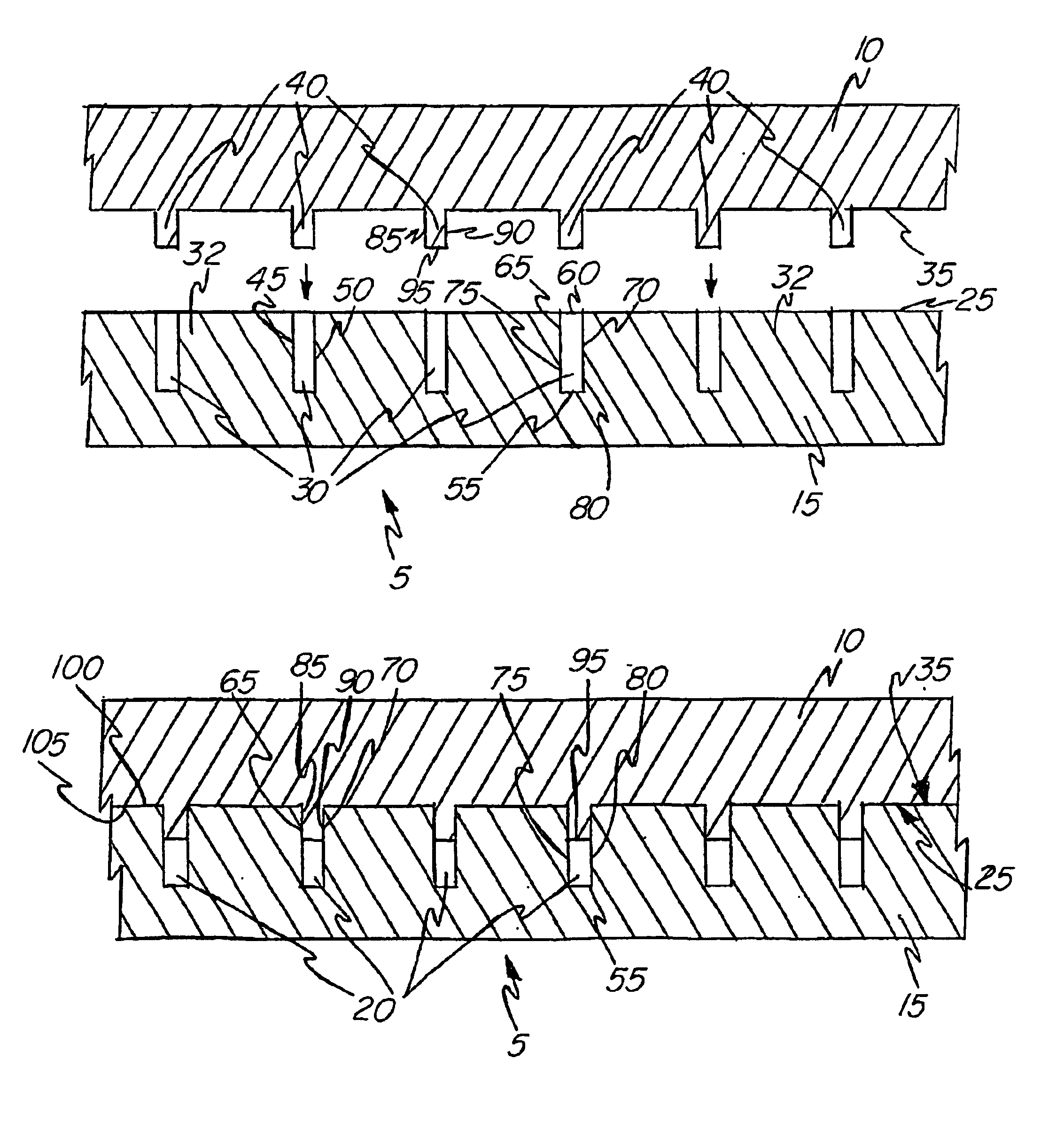
the present invention, depicted in FIGS. 7 and 8 as element 205, incorporates the protruding portions 240 formed in the backing plate material 215 along with the grooves 230. The grooves 230 comprise opposing sidewalls 245, 250, a bottom portion 255 and an opening 260. The grooves 230 define a plurality of islands 232 where the mating surface 225 remains. The protruding portions 240 extend from the mating surface 25 of the islands 232 and form a substantial “M” shape in cross section. As described in detail below, in this second embodiment, the bond between the target material 210 and the backing plate material 215 results independent of the formation of the cooling channels 220; the grooves 230 and the protruding portions 240 do not mate with one another. The consolidation method associated with this second embodiment results in cooling channels which can be made deeper than with use of the preferred embodiment for the same thickness of target material 210 or backing plate material...


PUM

PropertyMeasurementUnit
temperatureaaaaaaaaaa
temperaturesaaaaaaaaaa
temperatureaaaaaaaaaa

Abstract

The present invention pertains to low temperature pressure consolidation methods which provide for bonding of target material (10) to the backing plate material (15) capable of withstanding the stresses imposed by high sputtering rates. The sputter target assemblies (5) in accordance with the present invention are preferably comprised of target materials (10) and backing plate materials (15) having dissimilar thermal expansion coefficients and incorporate internal cooling channels (20). In the preferred embodiment, the resulting bond and the formation of the cooling channels (20) are cooperative.

Description

FIELD OF THE INVENTIONThe present invention relates to sputter target assemblies for use within sputtering systems. More specifically, the present invention pertains to sputter target assemblies with internal cooling channels which include a target material bonded, by low temperature pressure consolidation, to a backing plate material.BACKGROUND OF THE INVENTIONCathodic sputtering is widely used for the deposition of thin films, or layers, of material onto desired substrates. The sputtering process employs gas ion bombardment of a target material having a face formed of a material that is to be deposited as a thin film, or layer, on the given substrate. Ion bombardment of the target material not only causes atoms or molecules of the target material to be sputtered, it imparts considerable thermal energy to the sputter target assembly. This heat is typically dissipated by use of a cooling fluid circulated beneath, through or around a thermally conductive backing plate material that i...

Claims


Application Information

Patent Timeline
Patent Type & Authority Patents(United States)
IPC IPC(8): B23K20/02C23C14/34B21K25/00H01J37/34
CPCB21K25/00B23K20/02B23K20/023H01J37/3435H01J37/3497C23C14/3407Y10T428/24298Y10T428/24744Y10T428/24996Y10T428/249974Y10T428/249981C23C14/35
Inventor IVANOV, EUGENE Y.
Owner TOSOH SMD
Why Eureka
Try Eureka