Methods and systems employing infrared thermography for defect detection and analysis

a technology of infrared thermography and defect detection, applied in the direction of individual semiconductor device testing, optical radiation measurement, instruments, etc., can solve the problems of defect artifacts, difficult to discover and inability to detect defects using conventional test methods

Inactive Publication Date: 2005-01-11
MARENA SYST CORP
View PDF25 Cites 51 Cited by
  • Summary
  • Abstract
  • Description
  • Claims
  • Application Information

AI Technical Summary

Problems solved by technology

Each defect of FIG. 2, plus a number of others, adversely impacts the operation of pixel 110.
Unfortunately, many of these defects are difficult to discover using conventional test methods.
Some forms of excitation produce defect artifacts, which are differences between test and reference images that are caused by

Method used


Image

  • Methods and systems employing infrared thermography for defect detection and analysis
  • Methods and systems employing infrared thermography for defect detection and analysis
  • Methods and systems employing infrared thermography for defect detection and analysis

Examples


Embodiment Construction

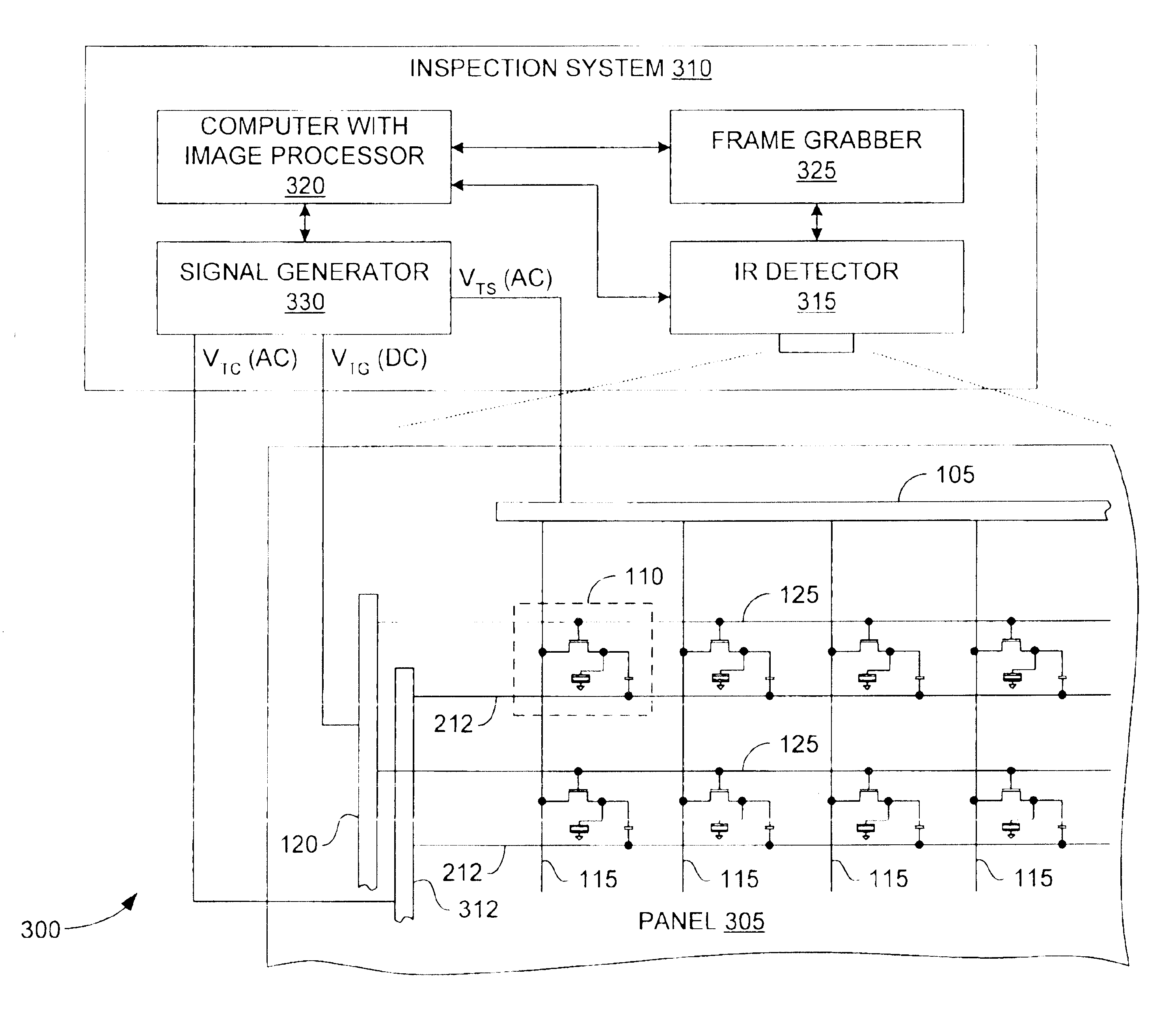
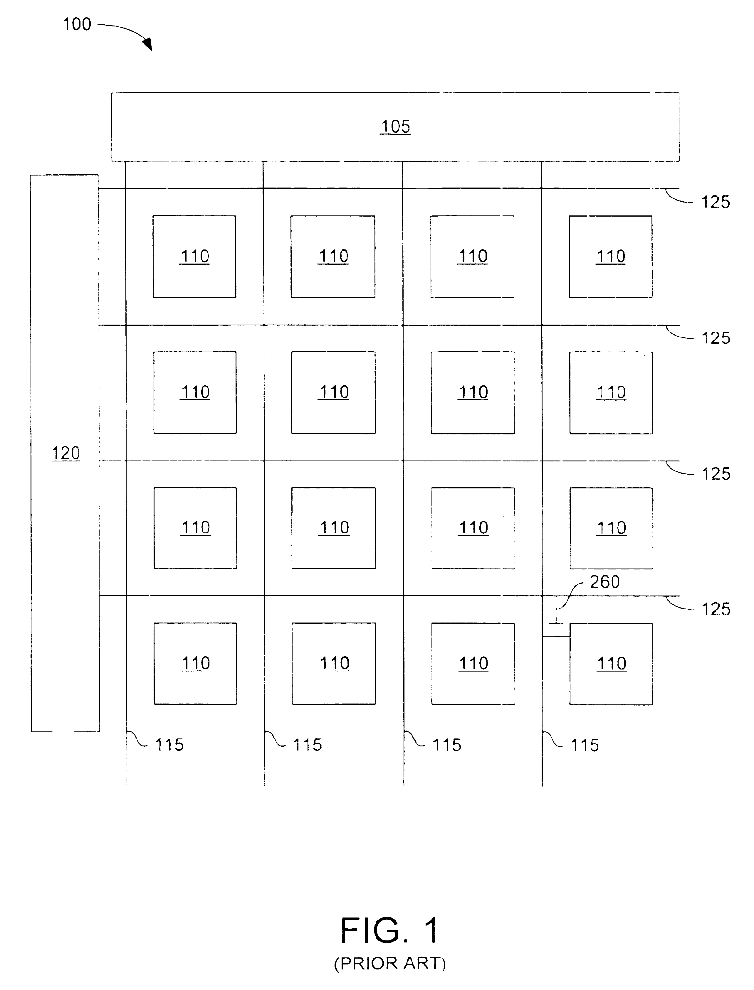
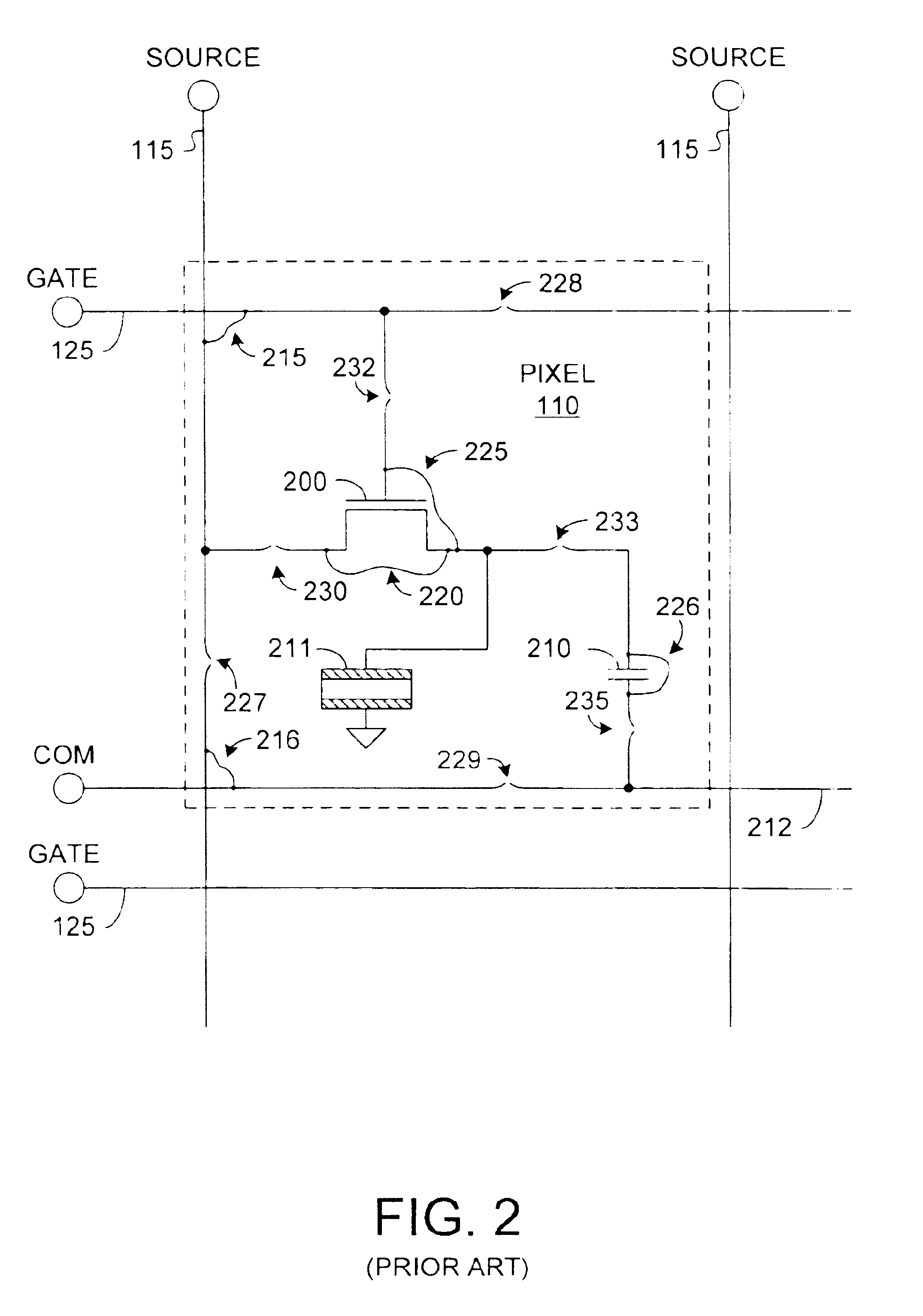
FIG. 3 depicts a test configuration 300, including a conventional panel 305 and an inspection system 310 adapted in accordance with an embodiment of the invention. Panel 305 is similar to panel 100 of FIGS. 1 and 2, like-numbered elements being the same or similar. Panel 305 includes a shorting bar 312 that is not depicted in FIG. 1, but is nevertheless conventional. Inspection system 310 includes an IR detector 315 (e.g., an IR camera) oriented over panel 305 to provide image data to a computer 320 via a frame grabber 325. An excitation source, signal generator 330, provides electrical test signals, or “test vectors,” to panel 310. The test vectors heat features of panel 310 to produce thermal characteristics useful in identifying defects.

Computer 325 controls signal generator 330 to apply test vectors to panel 305. These test vectors enhance the thermal contrast between defects and the surrounding features, and consequently allow IR detector 315 to acquire improved thermographic i...


PUM


Abstract

Described are methods and systems for providing improved defect detection and analysis using infrared thermography. Test vectors heat features of a device under test to produce thermal characteristics useful in identifying defects. The test vectors are timed to enhance the thermal contrast between defects and the surrounding features, enabling IR imaging equipment to acquire improved thermographic images. In some embodiments, a combination of AC and DC test vectors maximize power transfer to expedite heating, and therefore testing. Mathematical transformations applied to the improved images further enhance defect detection and analysis. Some defects produce image artifacts, or “defect artifacts,” that obscure the defects, rendering difficult the task of defect location. Some embodiments employ defect-location algorithms that analyze defect artifacts to precisely locate corresponding defects.

Description

BACKGROUNDElectrical circuits, such as printed circuit boards (PCBs), integrated circuits, and flat-panel displays (FPDs), may be tested for defects using infrared (IR) thermography. In general, power is applied to a device under test (DUT) to heat various of the device features. An infrared detector then captures a test image of the heated DUT. The resulting image, a collection of pixel-intensity values spatially correlated to the imaged object, is then compared with a similar collection of reference image data. Differences between the test and reference data, typically stored as a “composite image,” indicate the presence of defects.Defect identification algorithms analyze composite images to automatically identify defects, and consequently improve throughput and quality in device manufacturing. Examples of such inspection systems include, but are not limite to, inspection of FPDs, PCBs, MEMS-based devices, semiconductor devices, and biomedical specimen. One purpose of such systems...

Claims


Application Information

Patent Timeline
IPC IPC(8): G01R31/28G01R31/308
CPCG01R31/308G01N25/72G01R31/26G01R31/3183
Inventor ENACHESCU, MARIANBELIKOV, SERGEY
Owner MARENA SYST CORP
Why Eureka
Try Eureka