Vertebral body end plate cutter

a technology of end plate cutter and vertebral body, which is applied in the field of vertebral body end plate cutter, can solve the problems of not having the capacity to adequately stabilize the spine, not having initial strength, and contributing to varying degrees of spinal instability, etc., and achieves the effects of simple manufacturing, simple use, and convenient vertebral interbody fusion

Inactive Publication Date: 2005-01-11
SUDDABY LOUBERT
View PDF2 Cites 211 Cited by
  • Summary
  • Abstract
  • Description
  • Claims
  • Application Information

AI Technical Summary

Benefits of technology

It is the object of this invention to provide an exact, limited and reliable method of end plate violation or disruption to facilitate vertebral interbody fusion. It is also intended that the device described herein be simple to manufacture and simple to use in daily clinical surgical disc's internal architecture leads to bulging, herniation or protrusion of pieces of the disc and eventual disc space collapse. Resulting mechanical and even chemical irritation of surrounding neural elements (spinal cord and nerves) cause pain, attended by varying degrees of disability. In addition, loss of disc space height relaxes tension on the longitudinal spinal ligaments, thereby contributing to varying degrees of spinal instability such as spinal curvature or lithesis.

Problems solved by technology

In addition, loss of disc space height relaxes tension on the longitudinal spinal ligaments, thereby contributing to varying degrees of spinal instability such as spinal curvature or lithesis.
While cancerous bone appears ideal to provide the biologic components necessary for osseous union to occur, it does not initially have the strength to resist the tremendous forces that may occur in the intervertebral disc space, nor does it have the capacity to adequately stabilize the spine until long term bony union occurs.
For these reasons, many spinal surgeons have found that interbody fusion using bone alone has an unacceptably high rate of bone graft migration or even expulsion or nonunion due to structural failure of bone or residual degrees of motion that retard or prohibit bony union.

Method used


Image

  • Vertebral body end plate cutter
  • Vertebral body end plate cutter
  • Vertebral body end plate cutter

Examples


Embodiment Construction

)

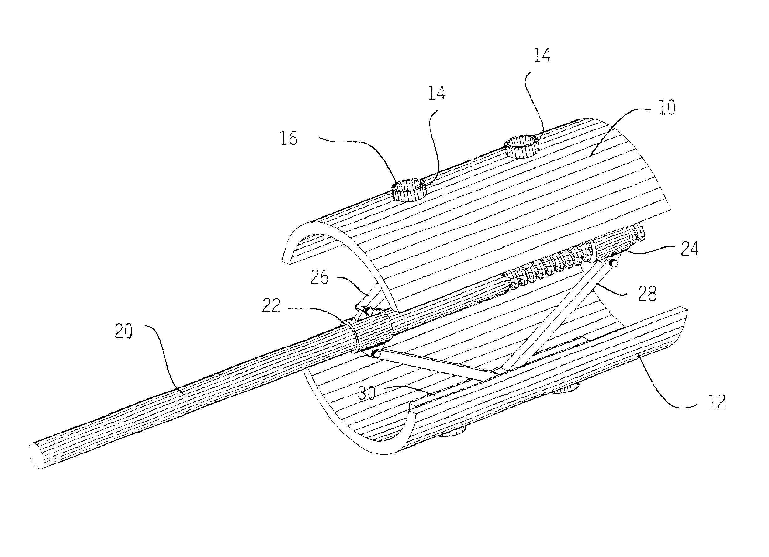
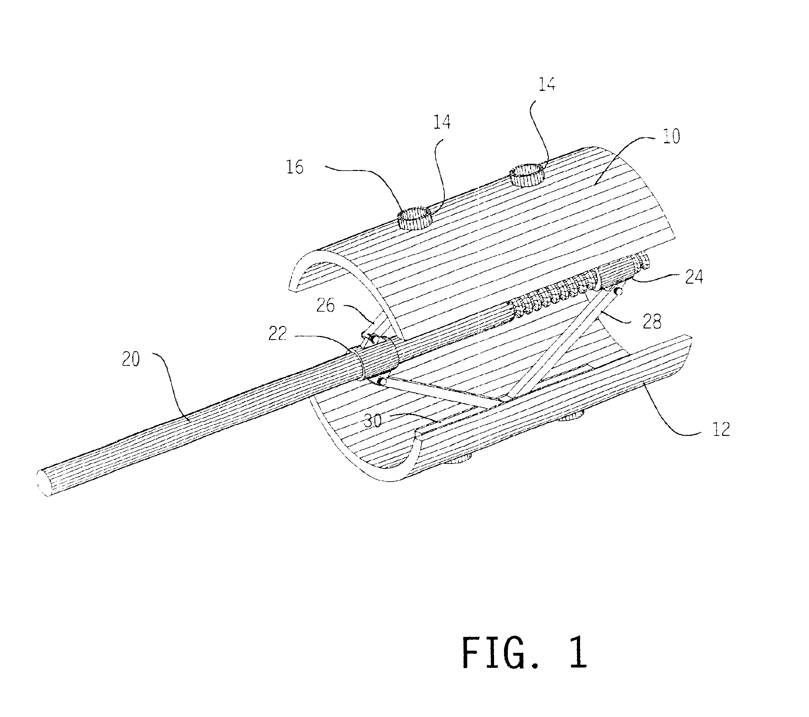
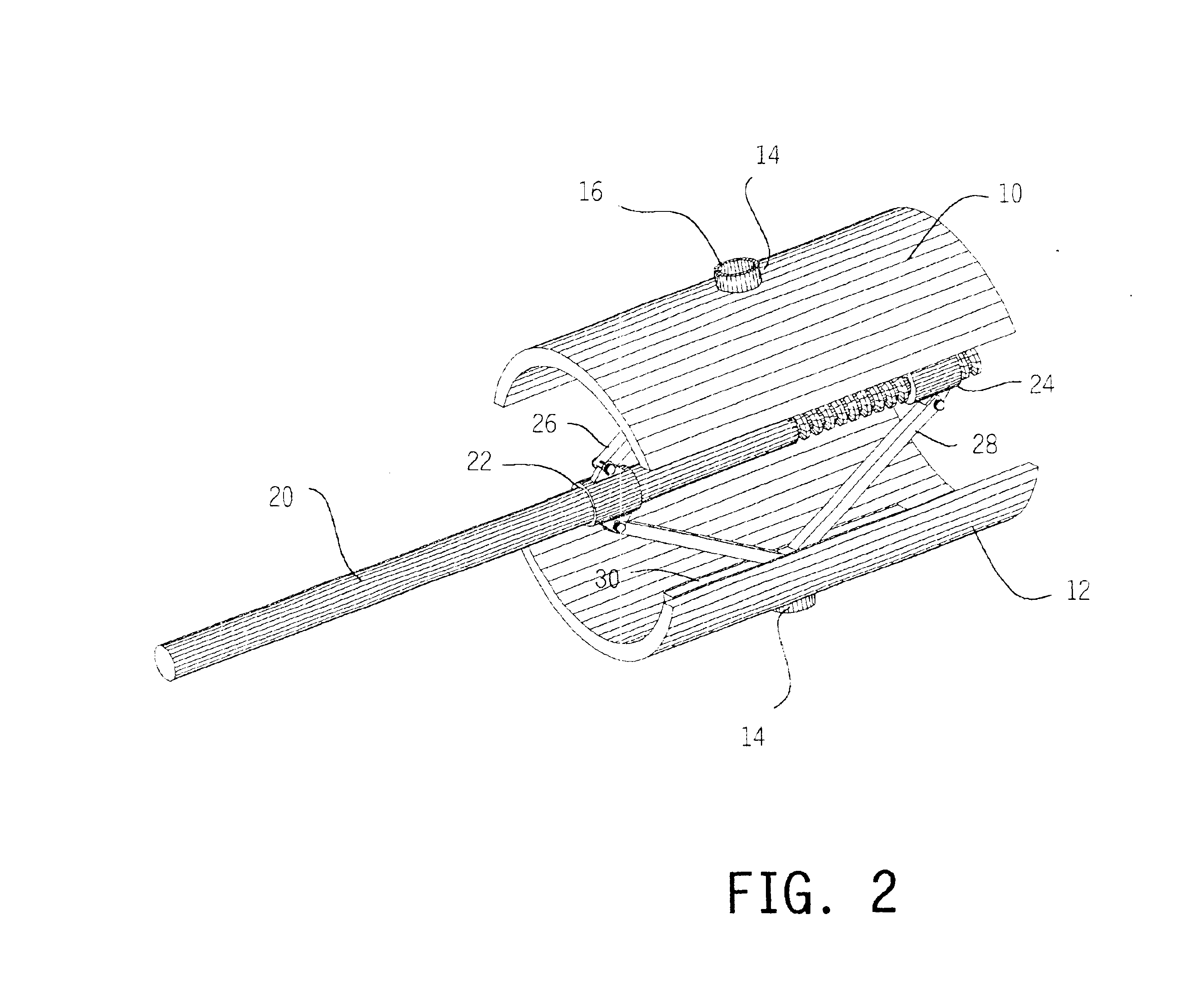
An end plate cutting tool suited for intervertebral fusion techniques includes at least two relatively movable elements such as the shells 10, 12 shown in FIGS. 1-3. Each of the shells has at least one (two in FIG. 1, one in FIG. 2) cutting structure 14 on its outer surface. In FIGS. 1 and 2, the cutting structure is a flange or band having a cutting edge 16 conforming in shape and location to bone growth apertures in cranial and caudal portions of a selected interbody fusion prosthesis 32 (shown in partial section in FIG. 4a).

The cutting structure 14 should be able to protrude 3-5 mm beyond the outer surface of the prosthesis, which has a wall thickness of 0.25-2.5 mm. So the design height of the cutting structure depends on the wall thickness of the prosthesis with which it is intended to be used.

The shells are supported on a jack screw mechanism including a shaft 20 threaded at its distal end, a fixed collar 22 seated in a groove knot shown) on the shaft, a traveling nut 24 enga...


PUM


Abstract

Precision recesses are cut in the end plates of vertebral bodies by inserting into the disc space a cutter having a pair of shell elements provided with cutting edges shaped to match bone growth apertures in a selected prosthesis. The remainder of the end plates are left undisrupted, to maximize bearing strength while promoting bone growth at the apertures.

Description

BACKGROUND OF THE INVENTIONThis invention pertains to an implement suitable for the precise violation of vertebral body end plates during the performance of interbody spinal fusion techniques.Of all animals possessing a backbone, human beings are the only creatures who remain upright for significant periods of time. From an evolutionary standpoint, this erect posture has conferred a number of strategic benefits, not the least of which is freeing the upper limbs for purposes other than locomotion. From an anthropologic standpoint, it is also evident that this unique evolutionary adaption is a relatively recent change and as such has not benefitted from natural selection as much as have backbones held in the horizontal attitude. As a result, the stresses acting upon the human backbone (or “vertebral column”), are unique in many senses, and result in a variety of problems or disease states that are peculiar to the human species.The human vertebral column is essentially a tower of bones...

Claims


Application Information

Patent Timeline
Patent Type & Authority Patents(United States)
IPC IPC(8): A61B17/32A61B17/16A61B17/00
CPCA61B17/1671A61B17/320016A61B2017/00261
Inventor SUDDABY, LOUBERT
Owner SUDDABY LOUBERT
Why Eureka
Try Eureka