Eureka AIR delivers breakthrough ideas for toughest innovation challenges, trusted by R&D personnel around the world.

Coolant for air-bag gas generator and production method therefor

a technology of gas generator and coolant, which is applied in the direction of chemical/physical processes, vehicle safety arrangements, synthetic resin layered products, etc., can solve the problems of no improvement in the unevenness of radial pressure loss of coolant, and uneven density of coolant in the axial direction. achieve the effect of stable operating outpu

Inactive Publication Date: 2005-01-11
DAICEL CHEM IND LTD +2
View PDF18 Cites 9 Cited by
  • Summary
  • Abstract
  • Description
  • Claims
  • Application Information

AI Technical Summary

Benefits of technology

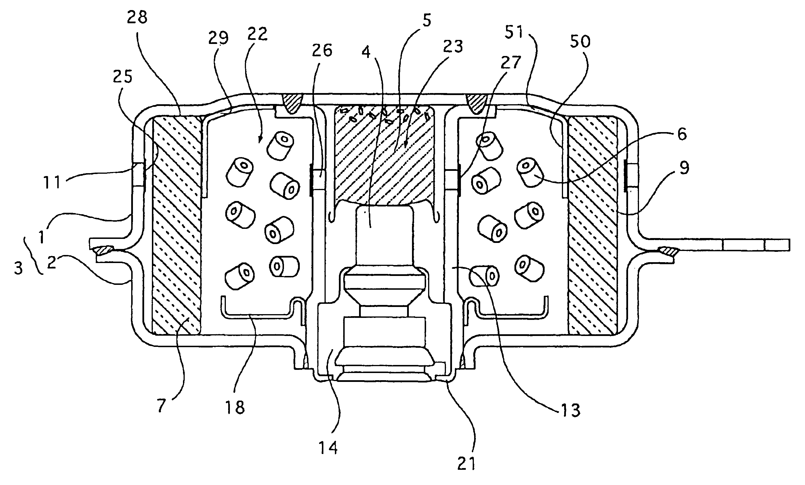
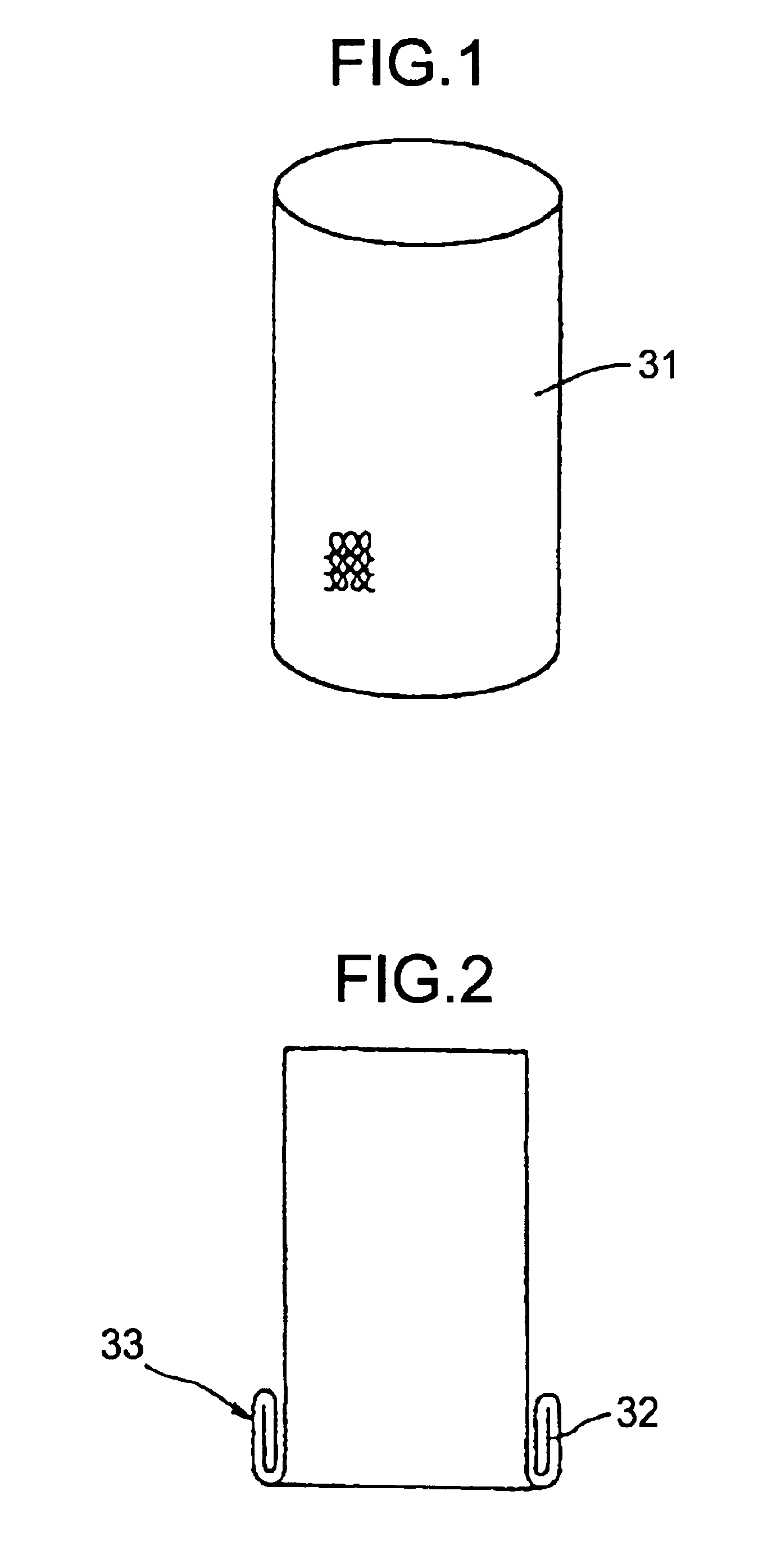
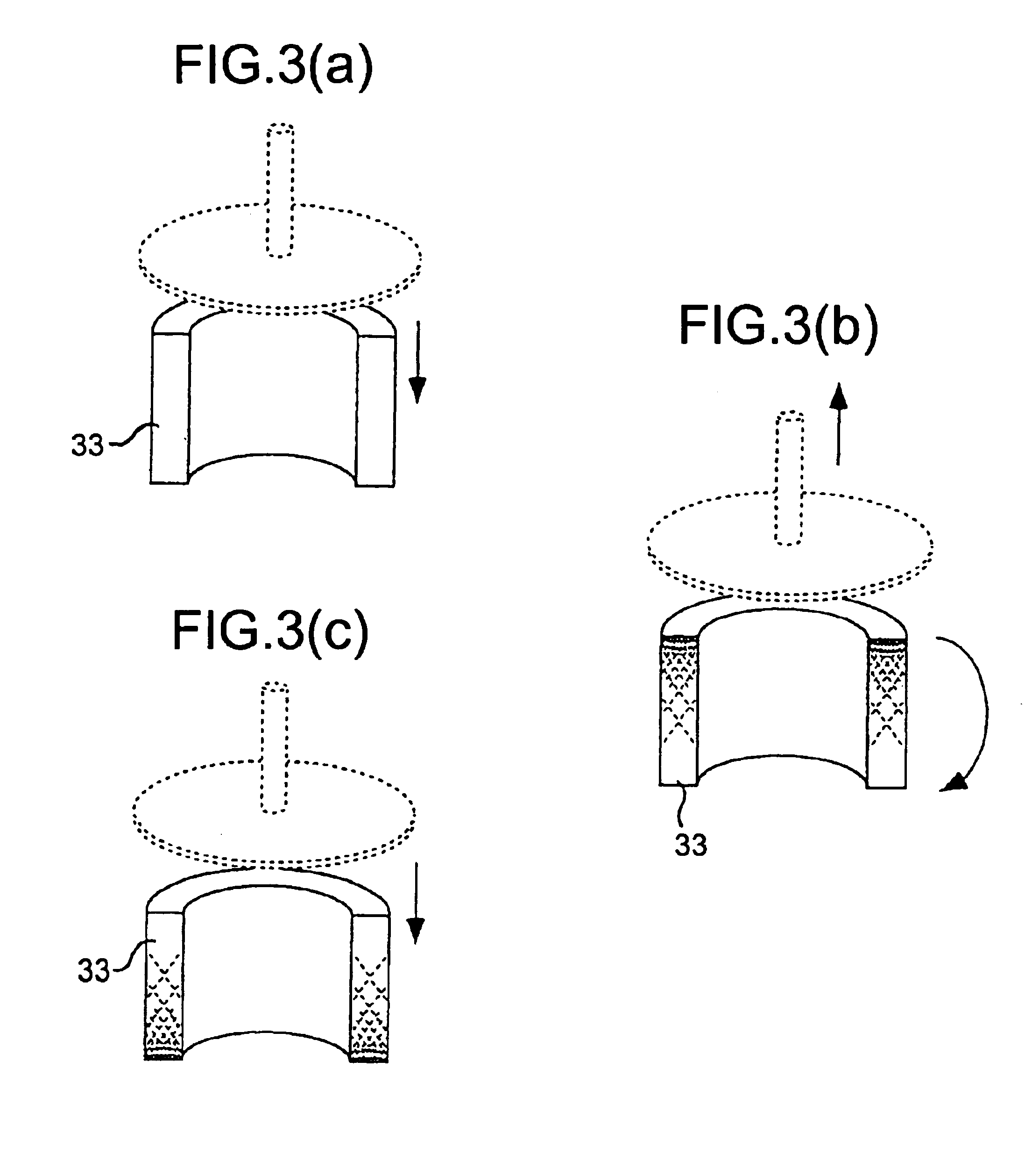
The present invention provides a coolant for an air bag inflator that solves the problems of conventional coolants, such as large unevenness in density and high pressure loss. The coolant is made of wire rods that are compressed in the axial direction to achieve a small difference in density between the upper and lower halves of 10 mmH2O or less. The coolant is cylindrical in shape and can be easily installed in the inflator without the need for a specific direction of installation. The coolant is designed to cool and purify the gas generated by the inflator. The technical effects of the invention include stable output performance and reduced temperature of the generated gas. The coolant is produced by laminating wire mesh and compressing it in the radial and axial directions. The resulting coolant has a small density difference in the axial direction and a low ventilation resistance, which ensures stable output performance. The coolant is made of stainless steel, which exhibits excellent corrosion resistance and can be selected from SUS304, SUS310S, and SUS316 (JIS Standard) based on its excellent properties.

Problems solved by technology

However, conventionally, no improvement concerning the unevenness in a radial pressure loss of the coolant has been found.
Because of this compression manner, the compressed side tends to shrunk more, and the density of the coolant means in the axial direction becomes uneven.
Therefore, the radial pressure losses in the axially upper and lower portion of the coolant cannot be uniformed.
The coolant means produced by such a conventional method has uneven pressure loss due to a difference in the density generated in the axial direction.
As a result, in the inflator using such a coolant means, output is varied due to the direction to which density of the coolant means is uneven (i.e., due to the difference of the pressure loss).

Method used


Image

  • Coolant for air-bag gas generator and production method therefor
  • Coolant for air-bag gas generator and production method therefor
  • Coolant for air-bag gas generator and production method therefor

Examples


example

Table 1 shows a result of a test of measuring a pressure loss carried out with the above-described coolant at the flow rate of 250 liters / minute. In this test, the apparatus shown in FIG. 6 is used and the following method is adopted.

TABLE 1Data of Pressure Loss of Coolant(mmaq)UpperLowerDifference between upperNo.Allportionportionand lower portions1 φ60 ×φ47 × h29.5 (250 L / min)Product manufactured under the current mass-production17462323213382711316413110411382612513402713613462422Ave.12.241.526.3Product manufactured by the new production (two timescompressing processes)112403192164232103174535104193938151738402614423210Ave.15.841.034.72 φ58 ×φ47 × h26 (250 L / min)Product manufactured under the current mass-production182818102103117143833211248352312592823669352411Ave.8.731.721.0Product manufactured by the new production (two timescompressing processes)1102828026282713103228449292905102723461128302Ave.9.328.727.5

the Upper portion: the upper side is pressed in the second compression...


PUM

PropertyMeasurementUnit
densityaaaaaaaaaa
diameteraaaaaaaaaa
densityaaaaaaaaaa

Abstract

The present invention provides a coolant for an air bag inflator in which unevenness in density in the axial direction is reduced even though the coolant is compressed in its axial direction.The coolant is a molded product made of wire rods and compressed in its axial direction. An absolute value of a difference between a radial pressure loss of the axially upper half portion of the coolant and a radial pressure loss of the axially lower half portion of the coolant is 10 mm H2O or less at a flow rate of 250 liters / minute under the atmosphere of 20° C.

Description

TECHNICAL FIELD TO WHICH THE PRESENT INVENTION BELONGSThe present invention relates to a coolant for an air bag inflator and a process for providing the same.RELATED ARTAn air bag apparatus is mounted to a vehicle such as an automobile in order to protect a passenger from the impact of collision. The air bag apparatus actuates an inflator when a sensor detects the impact, and form a cushion (air bag) between the passenger and the vehicle.The inflator used for the air bag apparatus is activated by an impact sensor detecting an impact, thereby discharging an operating gas (combustion gas) for inflating the air bag (bag body). The operating gas for inflating the air bag (bag body) is usually cooled and / or purified by coolant means accommodated in a housing of the inflator and then, the gas is discharged from a gas discharge port of the housing and introduced into the air bag.Conventionally, since the coolant means functionally needs to purify and cool the combustion gas generated due t...

Claims


Application Information

Patent Timeline
Patent Type & Authority Patents(United States)
IPC IPC(8): B01D39/12B01D39/10B60R21/26B60R21/264
CPCB01D39/12B60R21/2644Y10T29/49604Y10S29/902Y10S55/05Y10T442/2885B60R21/26B60R21/263B60R21/16
Inventor FUKUNAGA, KATSUAKIYAGI, SATOSHIOTA, MITSUNORICHIBA, MASAHIROCHIBA, EMIKO
Owner DAICEL CHEM IND LTD
Why Eureka
Eureka Blog
Learn More