Wavefront coding optics

a wavefront coding and optics technology, applied in the field of improved wavefront coding optics, can solve the problems of increasing the power of deterministic images, increasing the power of additive random noise, and impracticality of optics that produce mtfs with small changes with misfocus but also very low mtfs, so as to improve antialiasing characteristics, increase light gathering (and possibly spatial resolution), and improve the effect of antialiasing characteristics

Inactive Publication Date: 2005-01-11
CDM OPTICS +1
View PDF107 Cites 234 Cited by
  • Summary
  • Abstract
  • Description
  • Claims
  • Application Information

AI Technical Summary

Benefits of technology

An object of the present invention is to provide improved Wavefront Coding Optics, which retain the capacity to reduce focus-related aberrations, while producing high value MTFs, and to provide methods of designing such improved Wavefront Coding Optics.
To achieve higher MTFs, control misfocus and misfocus aberrations, and improve antialiasing characteristics, the central group of rays should be left unmodified by the Wavefront Coding Optics. In order to increase the light gathering (and possibly spatial resolution) of the full aperture system, the outer rays need to be modified. Only these outer rays need to be modified in order to increase the light gathering while keeping the depth of field and / or aliasing characteristics constant.

Problems solved by technology

In practice the amplification applied by the Image Processing function increases the power of the deterministic image but also increases the power of the additive random noise as well.
Optics that produce MTFs that have small changes with misfocus but also very low MTFs are impractical due to very large Noise Gain of the resulting digital filters.
Digital filters with large Noise Gain will produce final images that have unnecessarily high levels of noise.

Method used


Image

  • Wavefront coding optics
  • Wavefront coding optics
  • Wavefront coding optics

Examples


Embodiment Construction

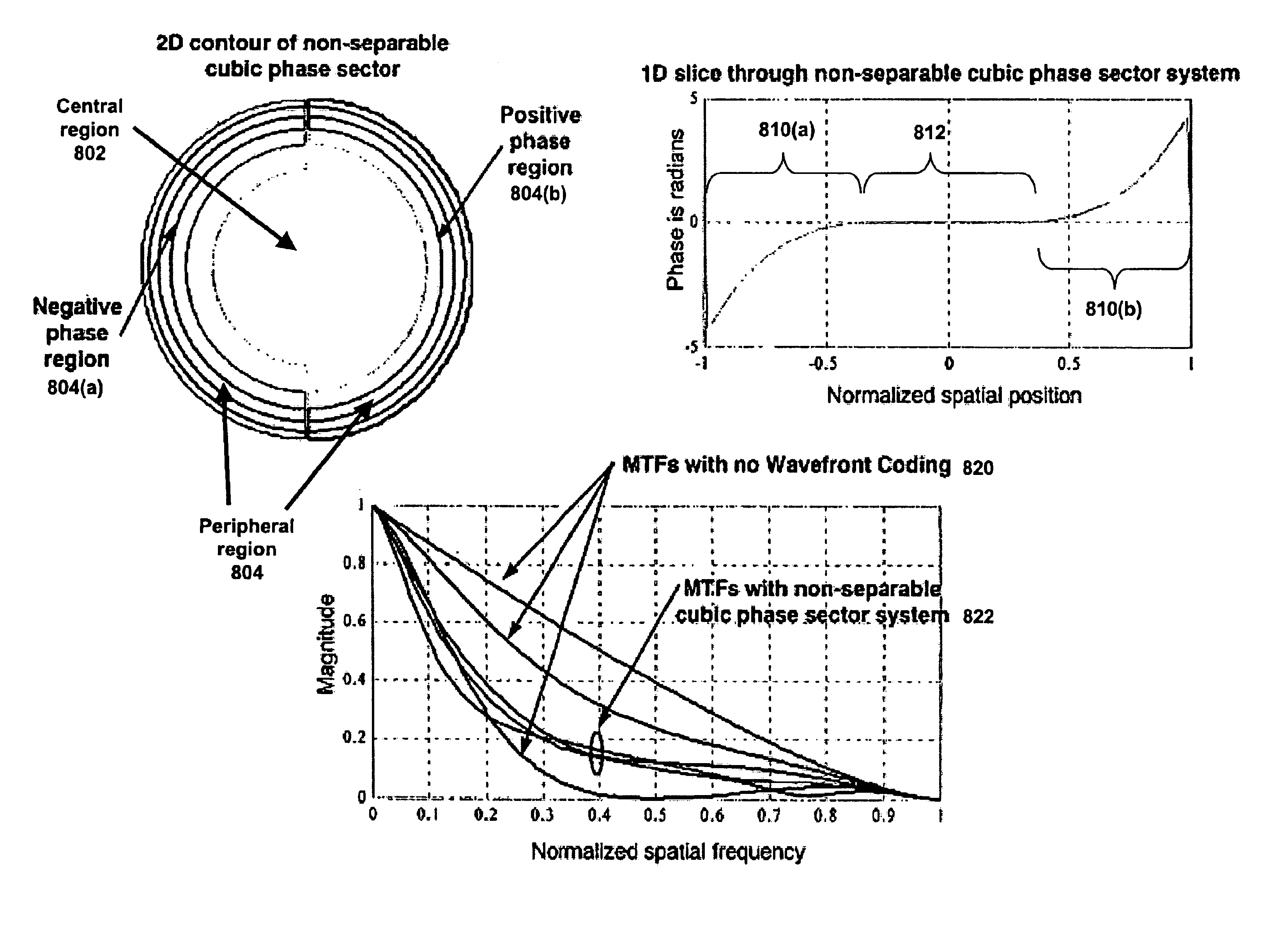
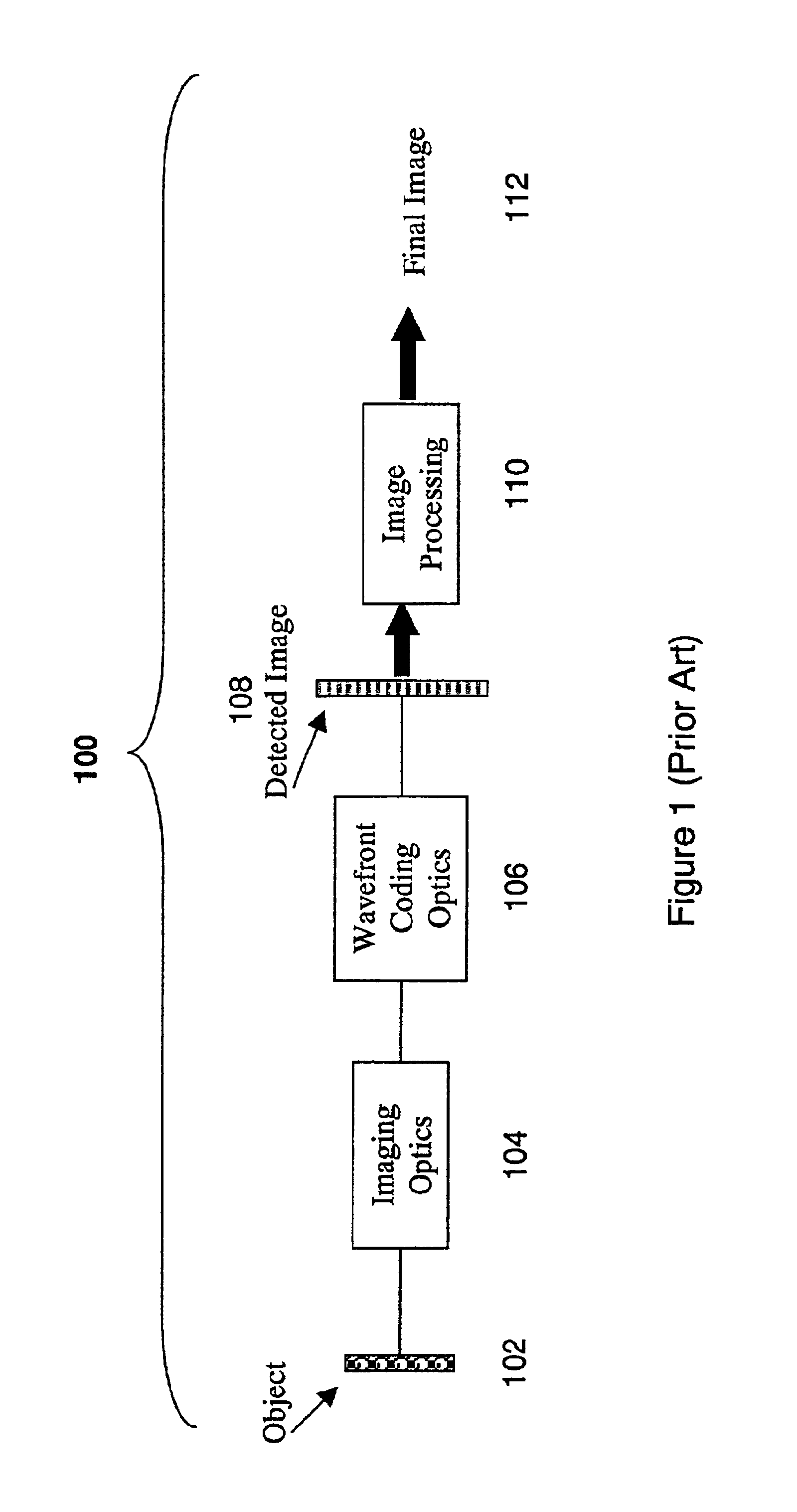
There are an infinite number of Wavefront Coding Optics that will reduce the variation in the resulting MTFs and PSFs of a given optical system due to misfocus or misfocus aberrations. Many of the possible optics are impractical in that the required Image Processing function 110 used to remove the Wavefront Coding blur from detected images would amplify the additive noise in practical images beyond an acceptable level. Improved forms of Wavefront Coding Optics that can control misfocus and misfocus aberrations, that can lead to higher MTFs, and that have improved antialiasing characteristics, as well as new methods of Wavefront Coding design, are shown in FIGS. 5 through 9. Use of these improved forms of Wavefront Coding Optics and design methods to control the misfocus aberrations with a Cooke triplet lens are shown in FIGS. 9 through 11.

The improved Wavefront Coding Optics according to the present invention share the characteristic that the central region of the applied phase prof...


PUM

PropertyMeasurementUnit
optical transfer functionaaaaaaaaaa
phase profileaaaaaaaaaa
phase functionaaaaaaaaaa

Abstract

Improved Wavefront Coding Optics, which apply a phase profile to the wavefront of light from an object to be imaged, retain their insensitivity to focus related aberration, while increasing the heights of the resulting MTFs and reducing the noise in the final images. Such improved Wavefront Coding Optics have the characteristic that the central portion of the applied phase profile is essentially flat (or constant), while a peripheral region of the phase profile around the central region alternately has positive and negative phase regions relative to the central region.

Description

BACKGROUND OF THE INVENTION1. Field of the InventionThis invention relates to improved Wavefront Coding Optics for controlling focus related aberrations, and methods for designing such Wavefront Coding Optics.2. Description of the Prior ArtWavefront Coding is a relatively new technique that is used to reduce the effects of misfocus in sampled imaging systems through the use of Wavefront Coding Optics which operate by applying aspheric phase variations to wavefronts of light from the object being imaged. Image processing of the resulting images is required in order to remove the spatial effects of the Wavefront Coding. The processed images are sharp and clear, as well as being relatively insensitive to the distance between the object and the detector.Wavefront Coding is also used to control general focus related aberrations to enable simplified design of imaging systems as well as to provide anti-aliasing in sampled imaging systems.The Wavefront Coding Optics taught and described in ...

Claims


Application Information

Patent Timeline
Patent Type & Authority Patents(United States)
IPC IPC(8): G02B26/06G02B26/00G02B27/46G02B5/00G02B27/00G06T1/00H04N1/028
CPCG02B26/06G02B27/46G02B27/0075G02B27/0025
Inventor DOWSKI, JR., EDWARD RAYMOND
Owner CDM OPTICS
Why Eureka
Try Eureka