System and method of implementing a buffer memory and hard disk drive write controller

a write controller and buffer memory technology, applied in the field of data processing systems, can solve the problems of disk drive units not being able to accept the next write command, delay in the complete signal of the command, etc., and achieve the effect of reducing the latency resulting from insufficient free space in the buffer memory, minimizing the seek time of the write head, and improving the overall performance of the data processing system

Inactive Publication Date: 2005-01-11
HITACHI GLOBAL STORAGE TECH NETHERLANDS BV
View PDF4 Cites 17 Cited by
  • Summary
  • Abstract
  • Description
  • Claims
  • Application Information

AI Technical Summary

Benefits of technology

[0019]Preventing further write commands from being sent when the buffer memory is full reduces a latency that results from insufficient free space in the buffer memory. The predetermined reference value is utilized to represent a typical size of a conventional write command that is sufficiently large to take into account multiple commands. This enables the reordering of write commands without introducing unnecessary latencies.
[0023]The external device will subsequently delay the issue of a next write command until sufficient free space exists in the buffer memory and the latency resulting from insufficient free space in the buffer memory is reduced, thereby improving the overall performance of a data processing system that utilizes a preferred embodiment of the disk drive unit of the present invention. If it is determined that a new write command and a queued write command are separated by at least a predetermined minimum distance, the new write command is inserted into the queue adjacent to the related queued write command, rearranging the order the queued write commands are written to the disk medium.
[0024]If the logical block addresses of the next and a queued write commands are separated by at least a predetermined minimum distance, it is possible to write the data corresponding to both the next and the related queued write commands to adjacent sectors on the disk medium. Consequently, it is also possible to form a write command group consisting of write commands separated by a predetermined minimum distance and optimize the write sequence of the write command group so as to minimize the seek time of the write head and reduce the writing time, thereby improving the writing performance of the disk drive unit.

Problems solved by technology

However, if there is not enough free space in the buffer memory to store a subsequent unit of write data, the command complete signal is delayed.
Therefore, the disk drive unit cannot accept the next write command until enough space has been freed in the buffer memory.

Method used


Image

  • System and method of implementing a buffer memory and hard disk drive write controller
  • System and method of implementing a buffer memory and hard disk drive write controller
  • System and method of implementing a buffer memory and hard disk drive write controller

Examples


Embodiment Construction

AY HIT in accordance to a preferred embodiment of the present invention;

[0045]FIG. 20 illustrates a chart depicting a BEST TAIL SKIP LENGTH hit status in accordance to a preferred embodiment of the present invention;

[0046]FIG. 21 depicts a chart for illustrating a relationship between buffer data and each hit status decided in FIG. 7 through FIG. 15 in accordance to a preferred embodiment of the present invention;

[0047]FIG. 22 illustrates a high-level logic flowchart for depicting another method of writing data in accordance to a preferred embodiment of the present invention;

[0048]FIG. 23 depicts a graph for denoting a set of relative scores in a high-end suite benchmark test when a reference value of a buffer free space is changed in accordance to a preferred embodiment of the present invention; and

[0049]FIG. 24 illustrates a graph for denoting a set of relative scores in a business suite benchmark test when the reference value of the buffer free space is changed in accordance to a...


PUM

PropertyMeasurementUnit
core frequenciesaaaaaaaaaa
sizeaaaaaaaaaa
clock frequencyaaaaaaaaaa

Abstract

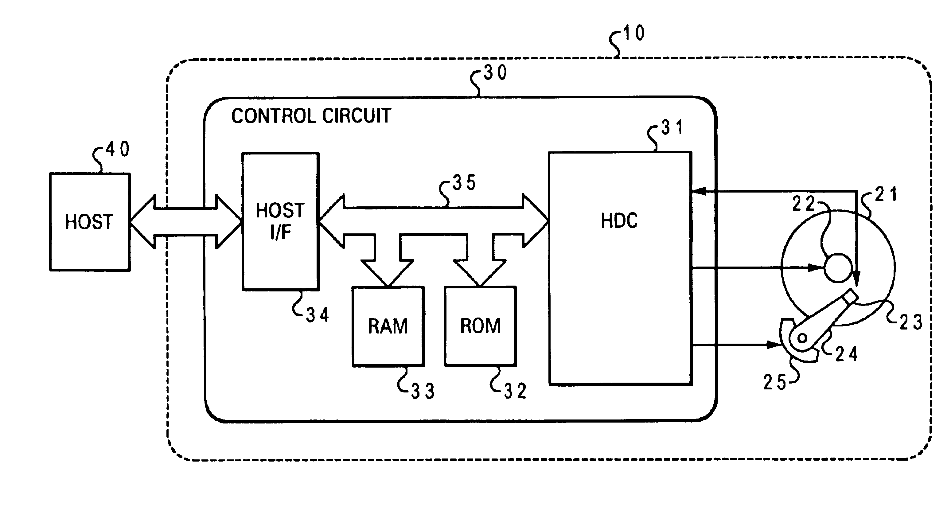
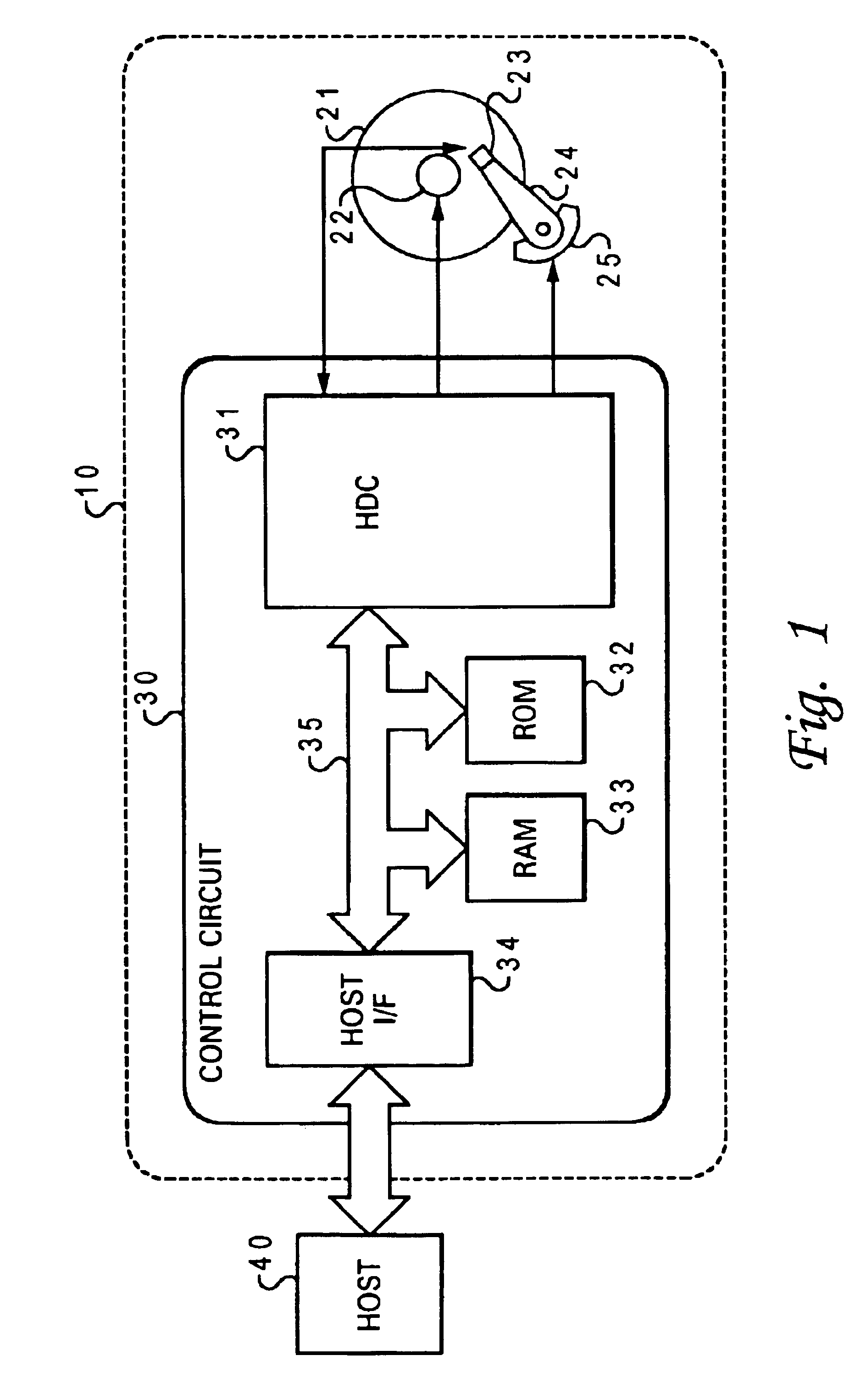
A method and system for writing data which includes the steps of: receiving a write command, storing associated data in a buffer memory, determining whether or not enough free space exists in the buffer memory to store a subsequent unit of write data, and sending a “command complete” signal to the external device, if it is determined that there exists enough free space to store a subsequent unit of write data. The disk drive unit includes: a random access recording medium, a command memory, a buffer memory, and a logic circuit for determining whether or not enough free space exists in the buffer memory to store a subsequent unit of write data, with a predetermined reference value representing the amount of free space occupied by a typical unit of write data.

Description

BACKGROUND OF THE INVENTION[0002]1. Technical Field[0003]The present invention relates in general to the field of data processing systems, and more particularly, the field of data processing systems utilizing a non-volatile memory. Still more particularly, the present invention relates to a system and method of reducing latency in data processing systems utilizing a non-volatile memory.[0004]2. Description of the Related Art[0005]In recent years, processing speeds in computer systems have increased exponentially. Processors with core frequencies of over one gigahertz have become common. However, to take full advantage of modem day processors, all aspects and components of a computer system must be improved. Most modem computer systems utilize hard disk drive technology, as well as random access memory (RAM) and read-only memory (ROM).[0006]Frequently, in today's computer systems, a hard disk drive is utilized as a low-cost, high-capacity data storage device. Unfortunately, hard disk...

Claims


Application Information

Patent Timeline
Patent Type & Authority Patents(United States)
IPC IPC(8): G06F3/06G11B20/10
CPCG06F3/0601G06F2003/0691G06F3/0656
Inventor YAMADA, SHUJI
Owner HITACHI GLOBAL STORAGE TECH NETHERLANDS BV
Why Eureka
Try Eureka