Solution treatment unit

a technology of solution treatment and treatment unit, which is applied in the direction of cleaning process and apparatus, cleaning using liquids, chemistry apparatus and processes, etc., and can solve problems such as substrate contamination

Inactive Publication Date: 2005-01-18
TOKYO ELECTRON LTD
View PDF15 Cites 26 Cited by
  • Summary
  • Abstract
  • Description
  • Claims
  • Application Information

AI Technical Summary

Benefits of technology

According to the present invention, the inner container surrounding the outer periphery of the substrate with its upper and lower faces open is provided, whereby the treatment solution scattered from the substrate is caught by the inner container and falls on the bottom portion of the treatment container. Since the drain port is provided in the bottom portion, the treatment solution which has fallen on the bottom portion is drained from the drain port. Meanwhile, when the developing solution is supplied, for example, mist of the developing solution and the like are produced and cause the contamination of the substrate. Accordingly, it is required to exhaust the atmosphere in the treatment container from blow in accordance with gravitation at the time of treatment. In the present invention, the exhaust pipe is provided in the bottom portion of the treatment container, whereby the atmosphere in the treatment container can be exhausted suitably from below the treatment container. Moreover, the exhaust port of the exhaust pipe is provided to be open at the position higher than the bottom portion of the treatment container, whereby the entry of the treatment solution which has fallen on the bottom portion into the exhaust port is eliminated, and consequently the drain of the solution and the exhaust of the atmosphere can be performed separately without being mixed.

Problems solved by technology

Meanwhile, when the developing solution is supplied, for example, mist of the developing solution and the like are produced and cause the contamination of the substrate.

Method used


Image

  • Solution treatment unit
  • Solution treatment unit
  • Solution treatment unit

Examples


Embodiment Construction

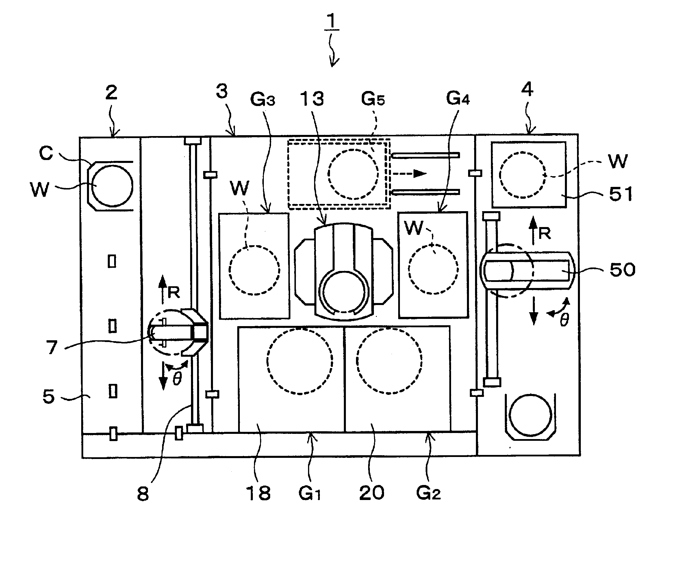
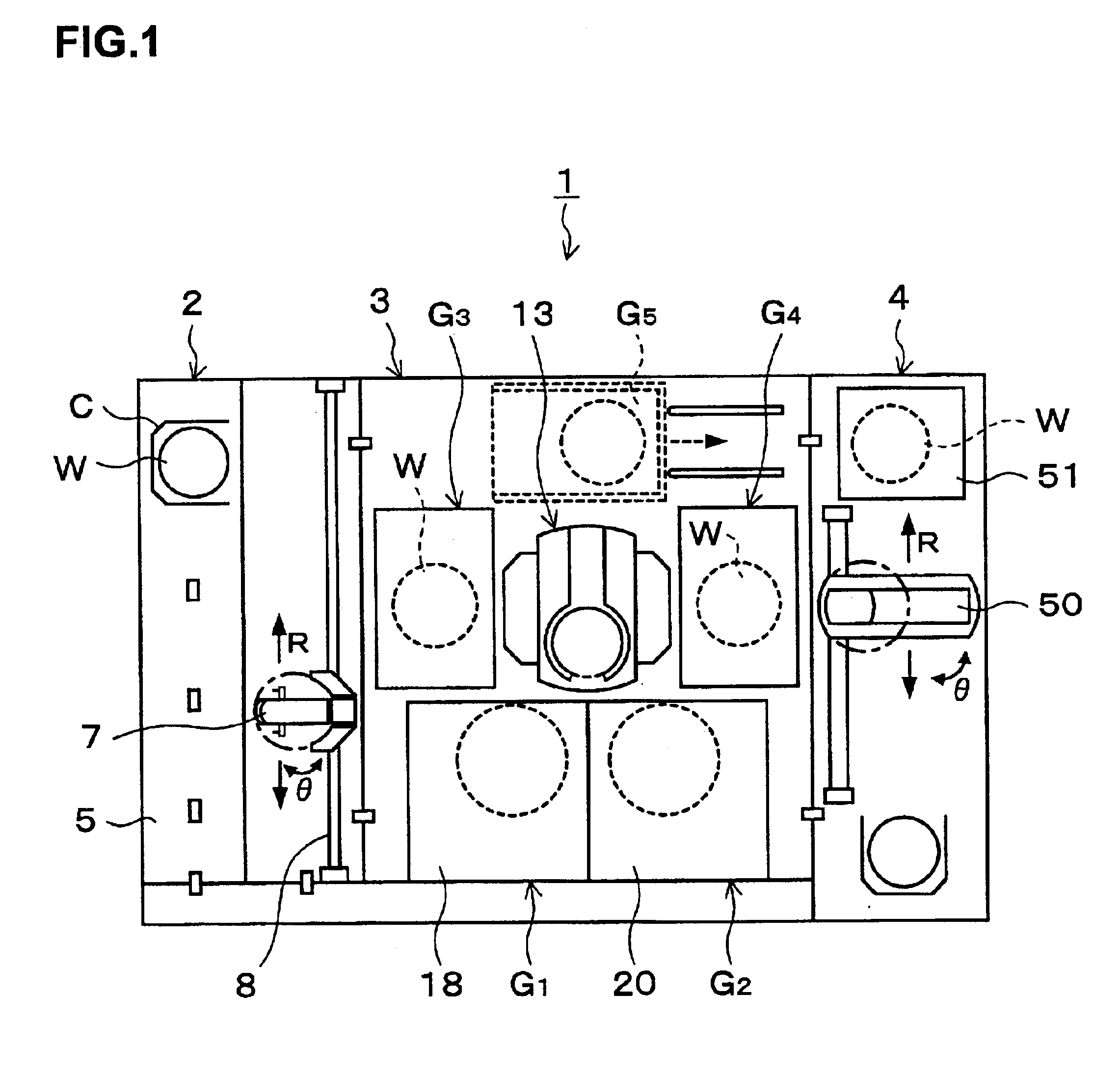
A preferred embodiment of the present invention will be explained. FIG. 1 is a plan view showing a sketch of a coating and developing treatment system 1 including a developing treatment unit as a solution treatment unit according to this embodiment, FIG. 2 is a front view of the coating and developing treatment system 1, and FIG. 3 is a rear view of the coating and developing treatment system 1.

As shown in FIG. 1, the coating and developing treatment system 1 has a structure in which a cassette station 2 for carrying, for example, 25 wafers W per cassette, as a unit, from / to the outside into / out of the coating and developing treatment system 1 and carrying the wafer W into / out of a cassette C, a processing station 3 in which various kinds of treatment units each for performing predetermined treatment for the wafers W one by one in coating and developing treatment processes are stacked in multiple tiers, and an interface section 4 for receiving / sending the wafer W from / to an aligner ...


PUM

PropertyMeasurementUnit
hydrophilicaaaaaaaaaa
timeaaaaaaaaaa
speedaaaaaaaaaa

Abstract

The present invention relates to a solution treatment unit for supplying a treatment solution to a substrate to treat the substrate within a treatment container, and an inner container surrounding an outer periphery of the horizontally held substrate with its upper and lower faces open is provided in the treatment container. An exhaust pipe for exhausting an atmosphere in the treatment container is provided in a bottom portion of the treatment container and inside the inner container. An exhaust port of the exhaust pipe is open at a position higher than the bottom portion. A drain port for draining the treatment solution in the treatment container is provided in the bottom portion. According to the present invention, the drain of a solution and the exhaust of an atmosphere can be performed separately without being mixed, and hence pressure loss of a fan on the factory side which performs an exhaust operation can be reduced, resulting in a reduction in excess power consumption.

Description

BACKGROUND OF THE INVENTION1. Field of the InventionThe present invention relates to a solution treatment unit for a substrate.2. Description of the Related ArtIn a photolithography process in semiconductor device fabrication processes, for example, resist coating treatment for coating the surface of a wafer with a resist solution to form a resist film on the wafer, exposure processing for exposing the wafer in a pattern, developing treatment for developing the exposed wafer, and the like are performed in sequence to form a predetermined circuit pattern on the wafer.A developing treatment unit in which the aforementioned developing treatment is performed includes, for example, a developing solution supply nozzle for supplying a developing solution to the wafer, a spin chuck capable of rotating the wafer while holding it, a cup surrounding the outer periphery of the wafer, and the like. The developing treatment is carried out in such a manner that after the developing solution is sup...

Claims


Application Information

Patent Timeline
Patent Type & Authority Patents(United States)
IPC IPC(8): B08B3/04H01L21/00G03F7/30H01L21/027
CPCB08B3/04H01L21/6715Y10S134/902H01L21/027
Inventor NAGAMINE, SHUICHI
Owner TOKYO ELECTRON LTD
Why Eureka
Try Eureka