Manufacturing apparatus of fiber reinforced composite member

a technology of fiber reinforced composite and manufacturing apparatus, which is applied in the direction of ceramic shaping cores, braids, drawing profiling tools, etc., can solve the problems of short coating life, disadvantageous weight of materials, low high-temperature strength, etc., and achieve the effect of enhancing productivity and reducing fiber loss

Inactive Publication Date: 2005-01-18
IHI CORP
View PDF15 Cites 2 Cited by
  • Summary
  • Abstract
  • Description
  • Claims
  • Application Information

AI Technical Summary

Benefits of technology

The present invention has been developed to solve the problem. Specifically, an object of the present invention is to provide a manufacturing method and apparatus of a fiber reinforced composite member, which can simultaneously manufacture a plurality of products, remarkably reduce fiber loss, and enhance productivity.

Problems solved by technology

However, this material is disadvantageously heavy because of its high density, low in high-temperature strength, and has a short coating life.
On the other hand, since ceramic is high in heat resisting properties but disadvantageously brittle, a ceramic matrix composite member (hereinafter abbreviated as CMC) has been developed by reinforcing the ceramic with ceramic fiber.
However, the conventional CMC cannot hold its hermetic properties and is disadvantageously low in resistance to thermal shock.
However, a problem is that it takes an impractically long time (e.g., one year or more) to completely fill the gap between the fibers by the CVI.
Moreover, in a high-temperature test or the like of the conventional CMC formed as described above, when a severe thermal shock (e.g., temperature difference of 900° C. or more) acts, the strength is drastically lowered, and the CMC can hardly be reused.
Therefore, the conventional ceramic matrix composite member (CMC) cannot substantially be used in the combustor (thrust chamber), the fuel piping or another component requiring the hermetic properties and resistance to thermal shock.
Therefore, as compared with the fiber used in the product portion, there are a large proportion of finally wasted fiber, much fiber loss, and the like, and this raises cost.
For example, although ceramic fiber used in the CMC product is expensive, in the conventional art, even with a relatively large CMC product (thrust chamber or the like), a fiber effective utilization ratio is only around 20%, and about 80% results in loss.
Therefore, particularly in the small-sized CMC product, there is a problem that much labor is required for setting / preparation or the like to the apparatus and that productivity is low.

Method used


Image

  • Manufacturing apparatus of fiber reinforced composite member
  • Manufacturing apparatus of fiber reinforced composite member
  • Manufacturing apparatus of fiber reinforced composite member

Examples


Embodiment Construction

A preferred embodiment will be described hereinafter with reference to the drawings.

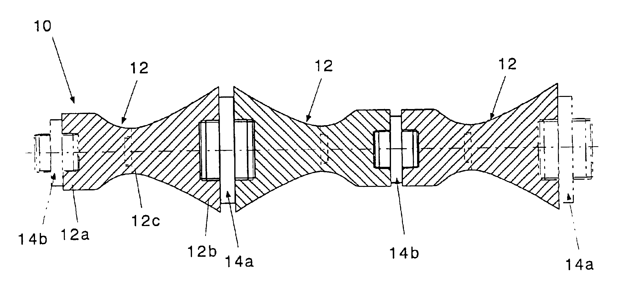
FIG. 3 is a schematic view of a mandrel applied to a manufacture apparatus of the present invention. As shown in FIG. 3, a mandrel 10 is an integral mandrel constituted by connecting both end portions 12a, 12b of a mandrel segment 12 for a unit product to one another, and linearly connecting a plurality of (three in FIG. 3) mandrel segments to one another.

Moreover, connection segments 14a, 14b are connected to both end portions 12a, 12b of the mandrel segment 12 via screws or the like, and the same end portions of the mandrel segment 12 (e.g., 12a and 12a, or 12b and 12b) are detachably connected to each other. Additionally, the connection segments 14a, 14b may be used to form the mandrel 10 as the integral mandrel of four or more mandrel segments 12.

Furthermore, the mandrel segment 12 is constituted to be dividable at a middle portion 12c which is smaller than both end portions 12a, 12b. Additionall...


PUM

PropertyMeasurementUnit
heat-resistant temperatureaaaaaaaaaa
temperatureaaaaaaaaaa
outlet diameteraaaaaaaaaa

Abstract

There is disclosed a method of connecting a plurality of mandrels to one another to constitute an integral mandrel 10, forming a fabric 1 on the surface of the integral mandrel, and infiltrating the formed fabric with matrix. A plurality of products can simultaneously be manufactured, and this can remarkably reduce fiber loss and enhance productivity.

Description

BACKGROUND OF THE INVENTION1. Field of the InventionThe present invention relates to a manufacturing method and apparatus of a fiber reinforced composite member, in which a plurality of products can simultaneously be manufactured.2. Description of the Related ArtIn order to raise the performance of a rocket engine using NTO / N2H4, NTO / MMH, and the like as impelling agents, heat-resistant temperature of a combustor (thrust chamber) is requested to be raised. For this purpose, a coated niobium alloy having a heat-resistant temperature of about 1500° C. has heretofore been used as a chamber material for many rocket engines. However, this material is disadvantageously heavy because of its high density, low in high-temperature strength, and has a short coating life.On the other hand, since ceramic is high in heat resisting properties but disadvantageously brittle, a ceramic matrix composite member (hereinafter abbreviated as CMC) has been developed by reinforcing the ceramic with ceramic ...

Claims


Application Information

Patent Timeline
Patent Type & Authority Patents(United States)
IPC IPC(8): B29C31/00B29B15/10B29B15/12B29C53/00B29C53/82B29C70/04B29C70/32B29C70/54B64G1/58C04B35/80
CPCB29C31/002B29C53/828B29C70/32B29C70/545B29L2031/3082B29C2793/00B29C2793/009D04C3/48
Inventor NAKAMURA, TAKESHI
Owner IHI CORP
Why Eureka
Try Eureka