Large-mode-field multilayer segmented cladding fiber

A large mode field and optical fiber technology, which is applied in clad optical fiber, multi-layer core/clad optical fiber, light guide, etc., can solve the problem of difficulty in making air holes in photonic crystal optical fiber, limited diameter of petal-shaped optical fiber core layer, large mode Solve the problems of low mass production yield of single-mode multi-core optical fiber in the field, and achieve the effect of improving single-mode transmission characteristics, reducing fiber loss, and realizing high-power single-mode laser output

Inactive Publication Date: 2017-12-22
BEIJING JIAOTONG UNIV
View PDF5 Cites 0 Cited by
  • Summary
  • Abstract
  • Description
  • Claims
  • Application Information

AI Technical Summary

Problems solved by technology

[0004] In order to overcome the limitation of the numerical aperture of the existing traditional optical fiber, the limited optical power of the single-core multi-doped rare earth ion region double-clad optical fiber, the difficulty of making the air hole of the photonic crystal fiber, and the low mass production yield of the single-mode multi-core optical fiber with large mode field, Due to defects such as the limited diameter of the core layer of the petal-shaped optical fiber, and to improve the single-mode transmission characteristics of the multi-groove optical fiber, the present invention proposes a multi-layer petal-shaped optical fiber with a large mode field area, which can suppress the attenuation of the optical fiber and reduce the loss of the optical fiber. Effectively improve the single-mode transmission characteristics of optical fiber

Method used


Image

  • Large-mode-field multilayer segmented cladding fiber
  • Large-mode-field multilayer segmented cladding fiber
  • Large-mode-field multilayer segmented cladding fiber

Examples


Embodiment 1

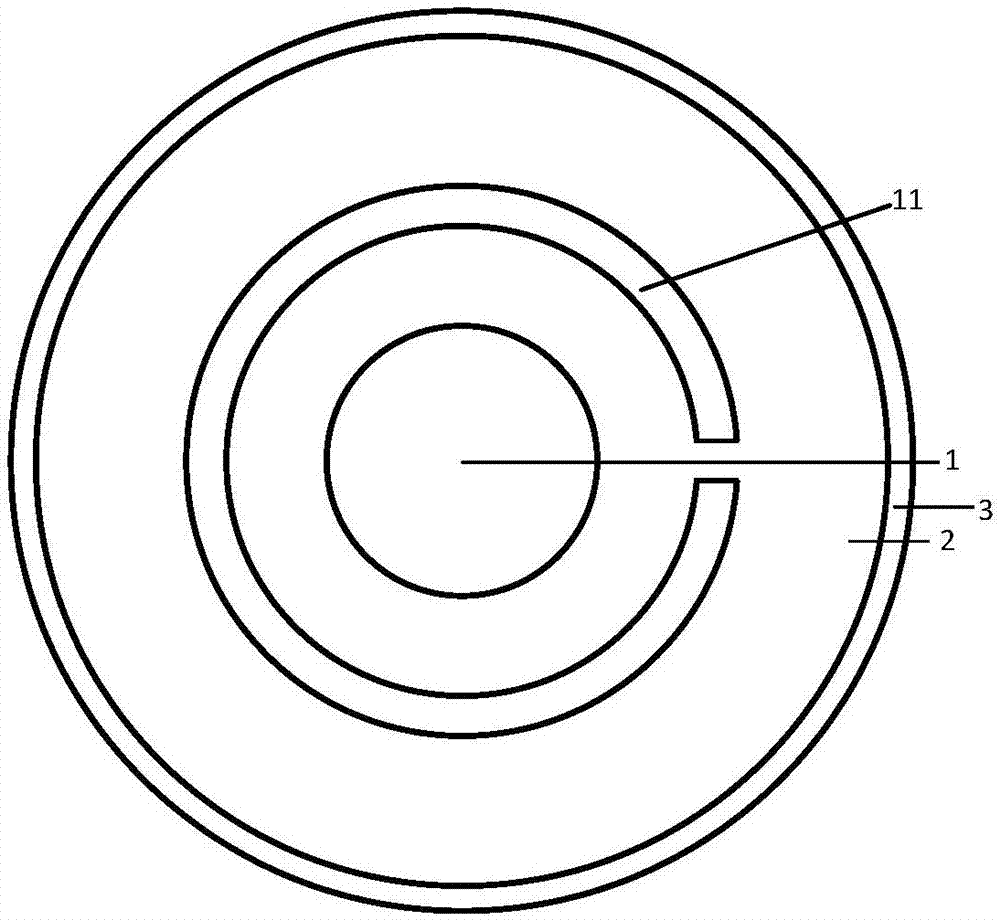
[0017] Large Mode Area 1 Suppression Channel 1 Layer Lobe Fiber, see figure 1 . The center of the optical fiber is a high-refractive-index fiber core (1), and outwards is an inner cladding (2). The inner cladding (2) contains a first high-refractive-index lobe (11), and the outermost layer is an outer cladding (3). In the example, M=1, N=1.

[0018] The refractive index of the high-refractive-index lobe (11) is equal to the refractive index of the high-refractive-index core (1); the refractive index of the high-refractive-index core (1) is greater than that of the inner cladding (2) and greater than that of the outer cladding (3) the refractive index.

[0019] The diameter of the high-refractive index core area (1) is 20 microns, the thickness of the high-refractive index lobe is 8 microns, the distance from the high-refractive index lobe to the fiber core is 10 microns, and the width of the suppression channel is 6 microns.

Embodiment 2

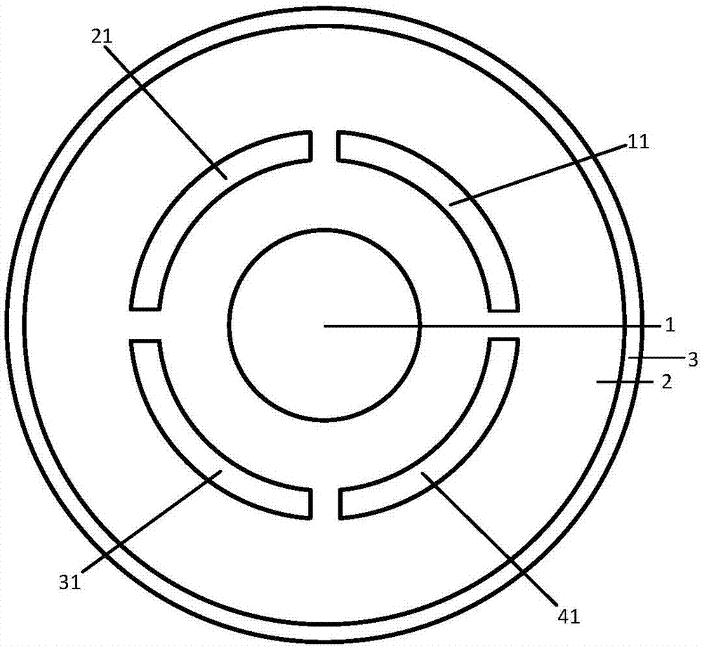
[0021] Large Mode Area 4 Suppression Channels 1 Layer Lobe Fiber, see figure 2 . The center of the optical fiber is a high-refractive-index core region (1), and outwards is an inner cladding (2). Layer (3), M=4, N=1 in this example.

[0022] The refractive index of the high-refractive-index lobes (11, 21, 31, 41) is equal to that of the high-refractive-index core (1), greater than that of the inner cladding (2), and greater than that of the outer cladding (3).

[0023] The diameter of the high-refractive index core area (1) is 20 microns, the thickness of the high-refractive index lobe is 8 microns, the distance from the high-refractive index lobe to the fiber core is 10 microns, and the width of the suppression channel is 6 microns.

Embodiment 3

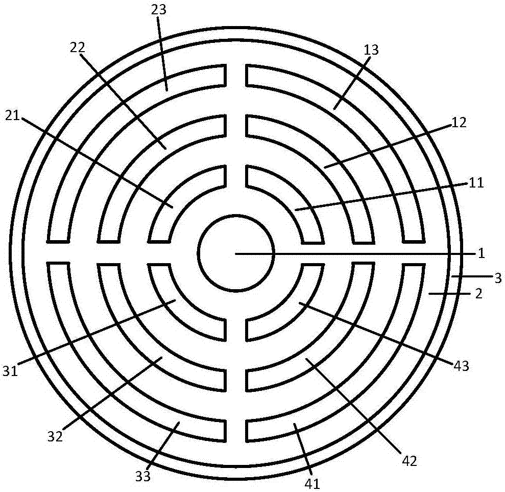
[0025] Large Mode Area 4 Suppression Channels 3-Layer Lobe Fiber, see image 3 . The center of the optical fiber is a high-refractive-index core region (1), and outwards is an inner cladding (2). The refractive index lobe (12, 22, 32, 42), the third layer of high refractive index lobe (13, 23, 33, 43), the outermost is the outer cladding (3), in this example M=4, N=3.

[0026] The refractive index of the high refractive index lobes (11, 21, 31, 41), (12, 22, 32, 42), (13, 23, 33, 43) is equal to the refractive index of the high refractive index core (1), greater than The refractive index of the inner cladding (2) is greater than that of the outer cladding (3).

[0027] The diameter of the high-refractive index core area (1) is 30 microns, the thickness of the high-refractive-index lobe is 8 microns, the distance between two adjacent high-refractive-index lobes is 10 microns, and the distance from the first high-refractive-index lobe to the fiber core is is 10 µm and the width...


PUM

PropertyMeasurementUnit
Diameteraaaaaaaaaa

Abstract

A large-mode-field multilayer segmented cladding fiber belongs to the field of large-power fiber amplifiers, lasers and special fibers. On the basis of a traditional multilayer trench fiber, low-refractive-index inhibition channels are adopted to divide high-refractive-index rings into multilayer segmented cladding cores, so mode loss of the fiber can be controlled and the single-mode transmission characteristics of the fiber can be improved. A high-refractive-index fiber core (1) is arranged in the center of the fiber. Low-refractive-index trenches and high-refractive-index rings of an inner cladding (2) are arranged in order from inside to outside. The layer number of the high-refractive-index rings is N (1<=N<=6). The high-refractive-index rings are segmented by M inhibition channels into N*M segmented cladding cores (1<=M<=4), which are (11, 21, 31, 41)......(16, 26, 36, 46) in order from inside to outside. The outmost layer is an outer cladding (3). The fiber of the invention can be manufactured through combination of an MCVD method and a glass rod filling method, and the inhibition channels in the high-refractive-index rings of a fiber prefabricated rod can be realized through a glass rod filling method.

Description

technical field [0001] The invention relates to a multilayer petal-shaped optical fiber with a large mode field area, belonging to the fields of high-power optical fiber amplifiers, lasers and special optical fibers. Background technique [0002] With the wide application of laser technology in material processing, space communication, laser radar, photoelectric countermeasures, laser weapons, etc., in order to obtain high-power and high-quality lasers, the single-mode output power is required to reach the MW or even GW level. Therefore, fiber lasers with advantages such as high conversion efficiency, low laser threshold, and good beam quality have been paid more and more attention. In 1988, since Snitzer et al. proposed double clad fiber [Snitzer, E., et al. Double clad, offset core Nd fiberlaser. Optical Fiber Sensors 1988.], based on this cladding pump laser and amplifier have achieved rapid development . In recent years, with the increase in the power of semiconductor ...

Claims


Application Information

Patent Timeline
IPC IPC(8): G02B6/02G02B6/036
CPCG02B6/02009G02B6/03622
Inventor 马绍朔裴丽郑晶晶
Owner BEIJING JIAOTONG UNIV
Why Eureka
Try Eureka