Roller thrust bearing

a technology of thrust bearings and rollers, applied in the direction of machines/engines, positive displacement liquid engines, mechanical equipment, etc., can solve the problems of increasing friction loss and wear, affecting the formation of oil film on the contact surface, and affecting the load capacity of bearings in use. , to achieve the effect of reducing differential slip and excellent flaking resistan

Inactive Publication Date: 2005-01-18
NTN CORP
View PDF29 Cites 26 Cited by
  • Summary
  • Abstract
  • Description
  • Claims
  • Application Information

AI Technical Summary

Benefits of technology

In view of the above the present invention contemplates a roller thrust bearing reducing a differential slip, free of significant friction and wear, and providing excellent flaking resistance.
In the roller thrust bearing arranged in contact with an inclined plate there is introduced a differential slip between a roller bearing ring and a roller. This differential slip negatively affects a formation of an oil film of a contact surface and impairs a lubricant in lubricity. In addition for example for a roller thrust bearing for an inclined-plate compressor for an automobile air conditioner, as aforementioned, a lubricant is thinned in use for example with a coolant of the air conditioner. This results in further impaired lubricity. Consequently, a rolling contact surface generates heat and a surface readily flakes or has similar damage. However, combining the crowned roller and the roller bearing ring having a surface layer with a high density of carbide distributed therein, can provide a remarkably excellent resistance to surface-flaking for example despite a condition for lubrication with a coolant of an automobile air conditioner and a lubricant mixed together. This resistance to surface-flaking can obtain a remarkably improved, synergetic effect that significantly exceeds an effect achieved by adding together effects of providing the roller, the roller bearing ring and the like with the above requirements separately.

Problems solved by technology

As such, a differential slip of the roller and the roller bearing ring disadvantageously causes generation of a stress at the roller's edge that is introduced between the roller bearing ring and the roller, which causes flaking of an edge of a rolling and running portion of the roller bearing ring that starts at a surface thereof.
Accordingly, the bearing in use encounters an increasingly severe condition in terms of load capacity.
As aforementioned, in a roller thrust bearing a differential slip of a roller and a roller bearing ring increases friction loss and wear that are caused at a contact surface.
Furthermore the contact surface's oil film formation is impaired, and at the roller's edge an edge stress between the roller bearing ring and the roller itself is readily introduced, which causes flaking of an edge of a rolling and running portion of the roller bearing ring that starts at a surface thereof.
This, however, reduces the roller's contact area and thus provides increased contact pressure.
Contact pressure at the contact surface thus increases, which results in impaired oil film formation and the exfoliation (flaking) for example disadvantageously occurs at the roller's radically outer surface.
The lubricant is thus disadvantageously reduced in amount.
As such, a worse oil film is formed than when a typical machine operating lubricant is used, and the bearing flakes earlier than expected.
These alternative flons are considered as being poorer in self-lubricity than conventionally used coolants.
With the alternative flon dissolved and thus mixed, the lubricant for example has a reduced kinematic viscosity, and the bearing has a significantly impaired oil film formation.
As such, the bearing would have a rolling element, a roller bearing ring and the like flaking, wearing or having a surface similarly damaged, resulting in reduced longevity.
However, because of its chemistry with the coolant, the lubricant can only be selected from a limited range and a significantly enhanced ability to form an oil film cannot be expected.
Increasing the amount of the lubricant in the coolant to enhance lubricity decreases the amount of the coolant and thus impairs the compressor's cooling ability.
Such a rotation rate and a load are also severer conditions, increasing a defect indicating damage of a surface of the bearing that is attributed to a differential slip.

Method used


Image

  • Roller thrust bearing
  • Roller thrust bearing
  • Roller thrust bearing

Examples


first embodiment

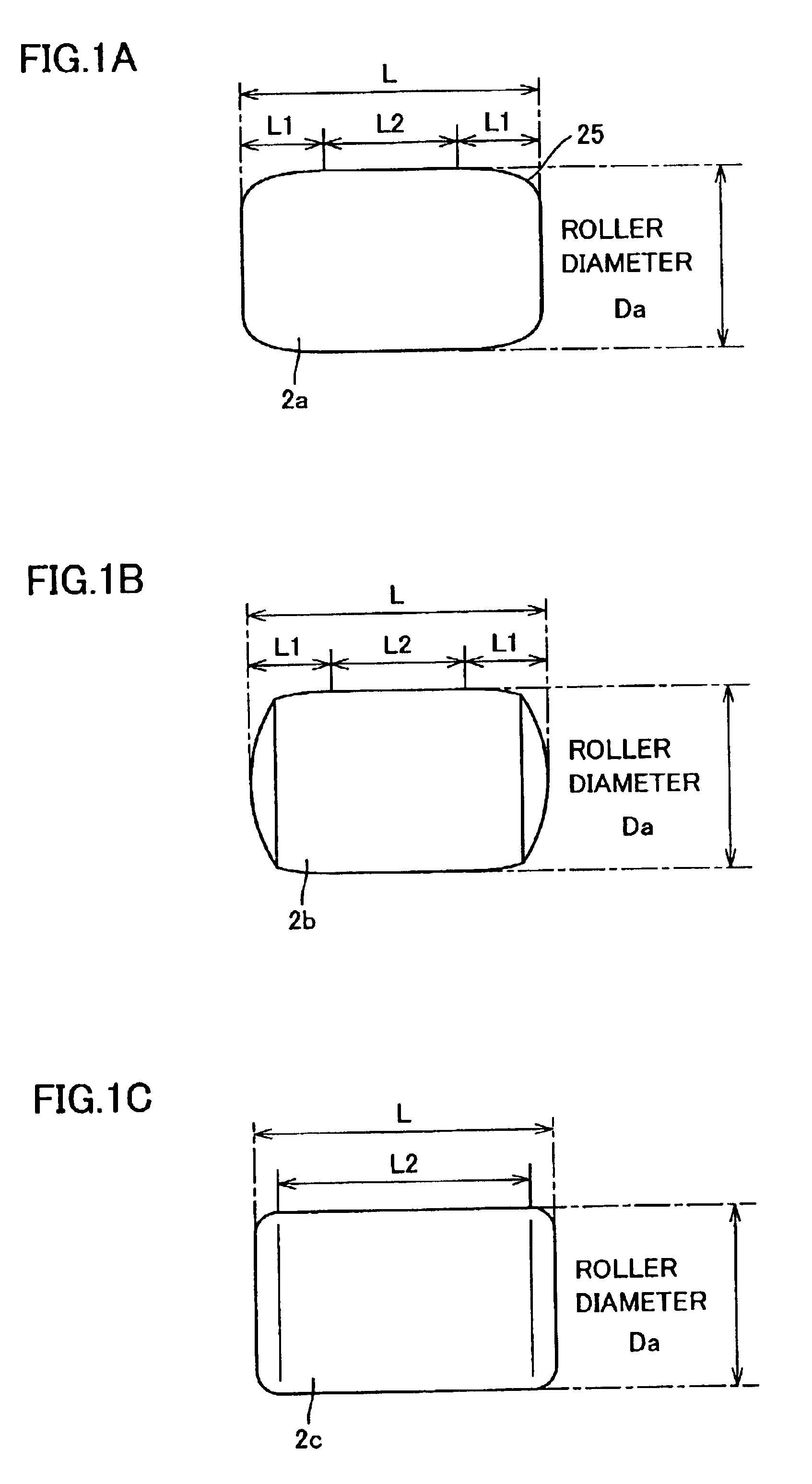
A longevity test was conducted using the above roller thrust bearing to verify that the present roller thrust bearing can contribute to a reduced differential slip of the roller's end surface and a reduced stress concentration in a vicinity of the roller's end, and a reduced friction loss and wear internal to the bearing to provide an increased longevity of an edge of a rolling and running portion against flaking.

The tested bearing had a roller having a diameter of 3 mm, a roller bearing ring having an inner diameter of 65 mm and an outer diameter of 85 mm. The test was conducted at a temperature of 60-80° C. with a load of 1,000 kgf at 500 rpm with a spindle oil VG2 (oil film parameter, lambda: 0.101) applied as a lubricant.

The test provided a result, as shown in Table 1, together with that of a comparative example, a needle roller thrust bearing having a standard roller and a standard cage. Longevity was represented by a 10% longevity of 10 test bearings. Note that the roller had ...

second embodiment

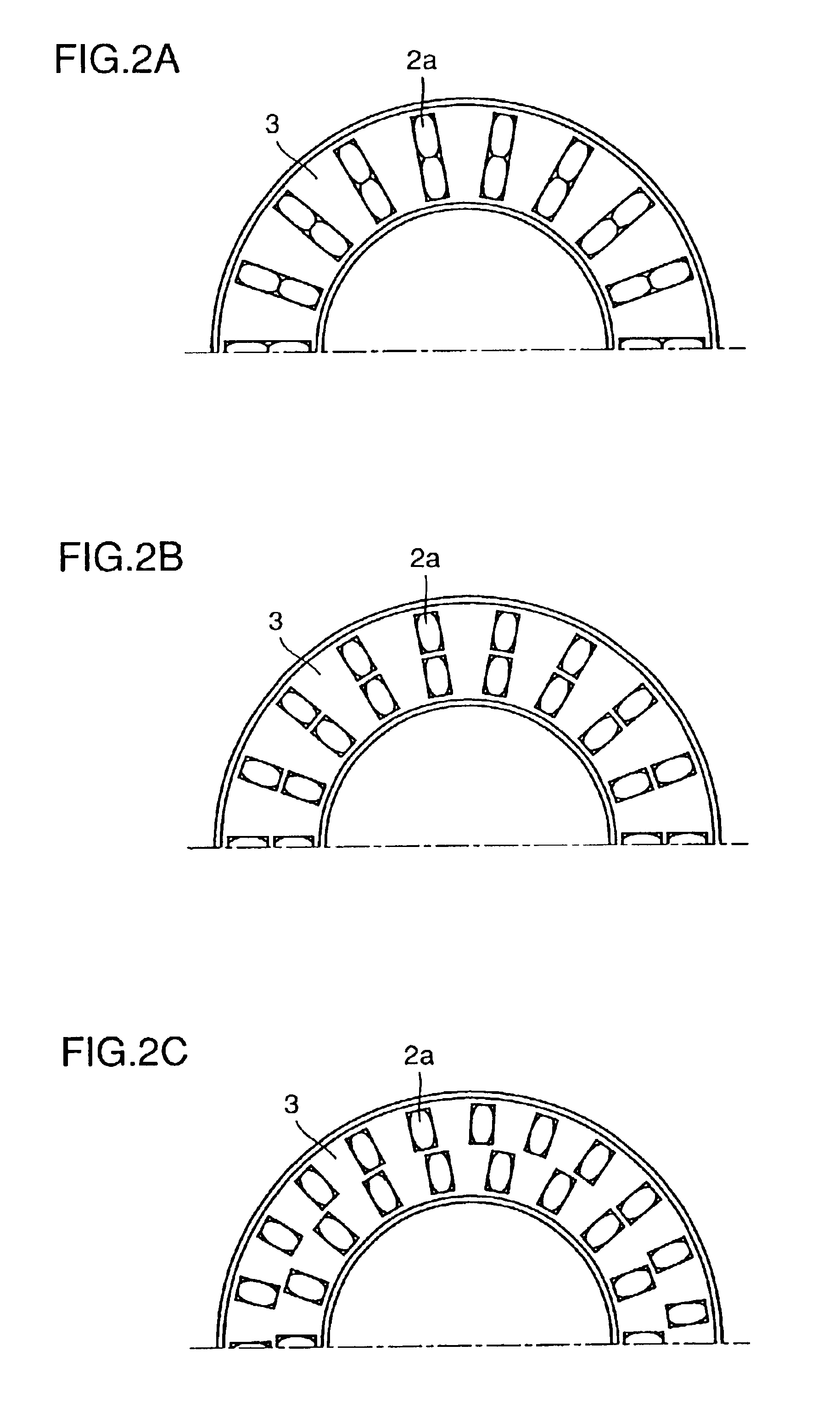
Two rows of crowned rollers varying in effective length and in geometry at their end surfaces were used in a test. The test provided a result, as shown in Table 2. A cage having pockets arranged radially in two rows or more (sample 5) prevented interference between rollers, enhanced the cage's ability to hold the rollers, reduced the rollers' skew to reduce friction loss and wear to provide an increased longevity against flaking, providing a ratio of 1.5 by the 10% longevity.

It is apparent from the test result that for two or more rows of rollers with a radially inner row of crowned rollers and a radially outer row of rollers less crowned than the inner rollers (sample 6) and two or more rows of rollers with a radially outer row alone formed of straight rollers (sample 7), reducing the contact surface pressure of the radially outer rollers, as compared to that of the radially inner rollers, can prevent flaking of the rollers' radially outer surfaces and a roller bearing ring's radia...

third embodiment

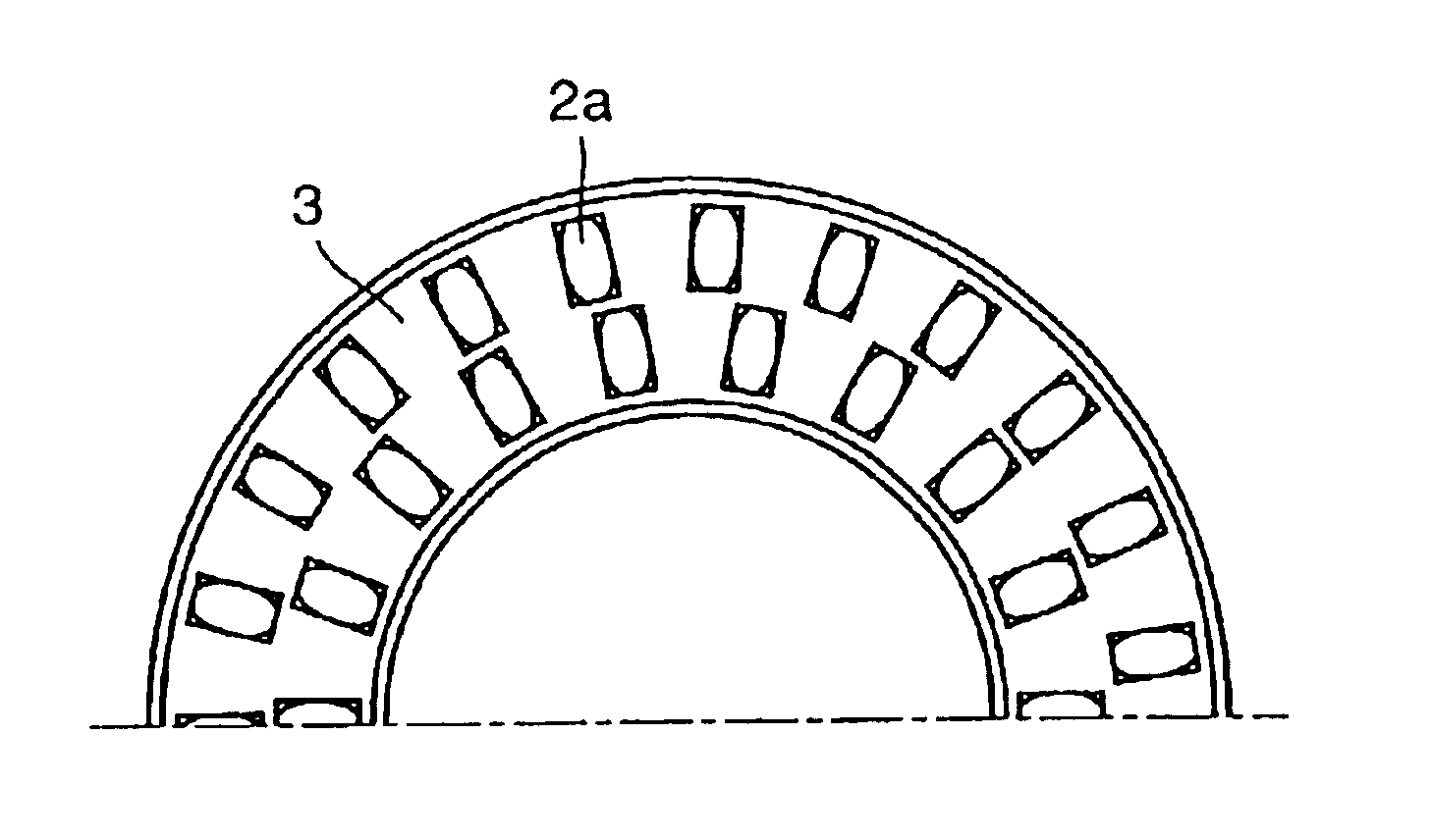
A test was conducted using a needle thrust bearing 1 formed of roller bearing rings 4 and 5, a rolling element (or roller) 2 arranged between the roller bearing rings, and a cage 3 holding and guiding rolling element 2, as shown in FIGS. 5A and 5B. The rolling element was a crowned rolling element. Rolling contact surfaces 6 and were formed between roller bearing rings 4 and 5 and roller 2. The needle thrust bearing had the roller bearing ring, the rolling element and the cage configured as shown in Table 3.

TABLE 3Specification ofRoller Bearing RingNo. ofcarbideSpecificationRatioPortion flakedMotor'sper unitcarbideof Roller10%inRollerCurrentareaper unitGeometryNo. ofLongevity10%BearingConsump-Sample No.(mm2)area (%)of RollerRollers(h)LongevityRingRollertion (A)3165400.5Straight1 row111  edge ofouter7  (standardinnersurfacebearing)surface3265400.5Straight2 rows282.5portionouter4.3(comparativeadjacent tosurface ofexample)radiallyradiallyinner rowouter roller3365400.5Crowned1 row544.9e...


PUM

PropertyMeasurementUnit
diameter sizeaaaaaaaaaa
depthaaaaaaaaaa
diameter sizeaaaaaaaaaa

Abstract

There is provided a roller thrust bearing providing reduced differential slip, free of significant friction and wear, and providing increased longevity against flaking. The present invention provides a thrust bearing in the form of a roller thrust bearing including at least two radially arranged rows of rollers and a cage holding the rollers, the rollers including at least one roller crowned.

Description

BACKGROUND OF THE INVENTION1. Field of the InventionThe present invention relates generally to roller thrust bearings including needle roller thrust bearings and particularly to thrust bearings arranged in rotative portions of electronic components of automobile transmissions (manual and automatic), transfers or compressors for automobile air conditioners and the like to support thrust loads exerted on the rotative portions.2. Description of the Background ArtWith reference to FIGS. 6A and 6B, a roller thrust bearing 1 includes a plurality of circumferentially, radially equally arranged rollers 2, a cage 3 formed in a circular ring and holding the plurality of rollers 2 rotatably, and outer and inner rings 4 and 5 serving as a roller bearing ring sandwiching and thus supporting the plurality of rollers 2 on their opposite sides. Outer and inner rings 4 and 5 are each formed in a circle formed of a metal plate having a sufficient hardness. Outer ring 4 has a circular ring surface 6 o...

Claims


Application Information

Patent Timeline
Patent Type & Authority Patents(United States)
IPC IPC(8): F16C33/30F16C33/46F16C33/48F16C33/58F16C33/54F16C33/64F16C33/34F04B27/10F16C19/22F16C19/30F16C19/38
CPCF04B27/1063F16C33/34F16C33/4635F16C33/48F16C33/543F16C33/547F16C33/64F16C19/305F16C23/088Y10T29/49693F16C2240/40F16C2240/50F16C2360/42Y10T29/49643Y10T29/49645Y10T29/49689Y10T29/49636F16C2360/00F16C19/38
Inventor TAMADA, KENJIMAEDA, KIKUOKAWAMURA, TOMOAKINAKASHIMA, HIROKAZUFUJITA, TAKUMISASABE, MITSUO
Owner NTN CORP
Why Eureka
Try Eureka