Zero thermal expansion material and practical component parts making use of the same

a technology of zero thermal expansion and component parts, applied in solid-state devices, inorganic chemistry, electrical apparatuses, etc., can solve the problems of inability to achieve high working precision, large lowering of performance, and in accordance with expansion and contraction, so as to achieve zero thermal expansion coefficient, less variation in characteristics, and high workability. the effect of precision

Inactive Publication Date: 2005-01-18
PANASONIC CORP
View PDF7 Cites 7 Cited by
  • Summary
  • Abstract
  • Description
  • Claims
  • Application Information

AI Technical Summary

Benefits of technology

An object of the present invention is to provide a material whose coefficient of thermal expansion is substantially zero over a wide temperature range (a zero thermal expansion material), and also to provide various materials and component parts making use of this materials and having good properties.
The present invention enables production of a zero thermal expansion material whose coefficient of thermal expansion is substantially zero. Since a ceramic material is used as the positive thermal expansion material, the coefficient of thermal expansion may little change even at a high temperature of 1,000° C. or more. This makes it possible to provide a zero thermal expansion material which is a heat-resistant material also having a high working precision.
Thus, when high frequencies in the millimeter wave range are used where, e.g., a component part has a length corresponding to wavelength at most, it is possible to actually provide electronic materials having a high-precision workability and also having a substantially zero coefficient of thermal expansion, and high-performance electronic component parts which may undergo less variations in characteristics due to temperature. In the filed of precision machines for which working precision is required in the order of microns, it is possible to provide good structural material and precision machine component parts substantially free of any expansion and contraction over a wide temperature range.

Problems solved by technology

However, it has not been reported that a method of producing such a material is applied to ceramic materials used widely in, e.g., high-frequency circuit component parts and the negative thermal expansion material and a ceramic material are simultaneously fired to produce a new low thermal expansion material.
Thus, conventional electronic materials or component parts and structural materials, which have positive coefficients of thermal expansion, inevitably cause expansion and contraction in accordance with changes in ambient temperature.
Even a slight error in size thus caused inevitably brings about a great lowering of performance in the case of electronic materials, precision machine component parts and so forth used in high-frequency circuit component parts.
Hence, such materials have had problems that not only any high working precision cannot be achieved but also electric and electronic properties tend to deteriorate.
In addition, where materials free of any expansion and contraction in a high-temperature condition are demanded, there has been a problem that the composite material comprised of an epoxy resin and a negative thermal expansion material as reported by Sleight et al. can not substantially materialize such materials.
More specifically, in the field of precision machines in which the working precision is required in the order of microns, the above composite material can not cope with its use in a high-temperature condition.

Method used


Image

  • Zero thermal expansion material and practical component parts making use of the same
  • Zero thermal expansion material and practical component parts making use of the same
  • Zero thermal expansion material and practical component parts making use of the same

Examples


embodiment 1

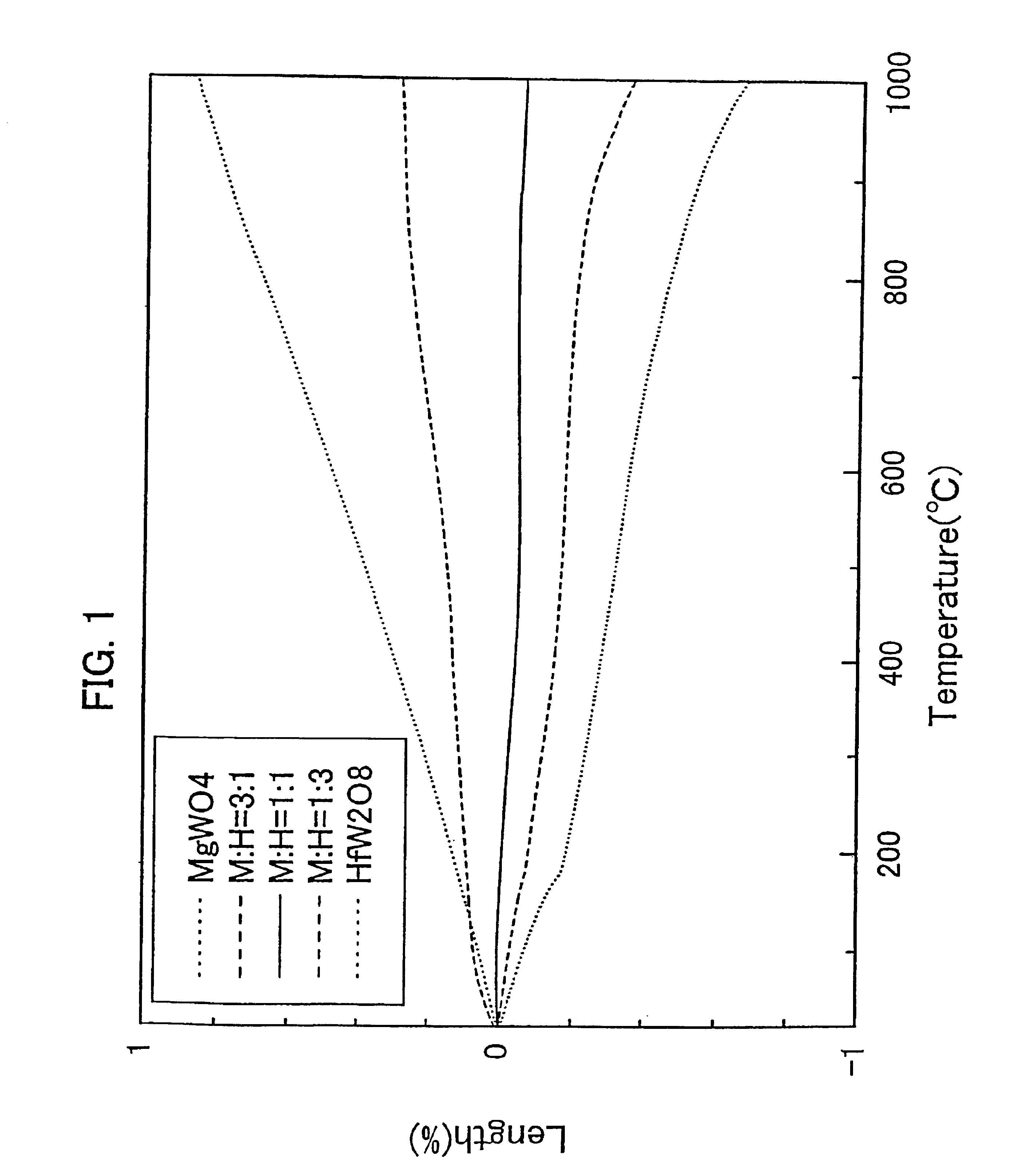
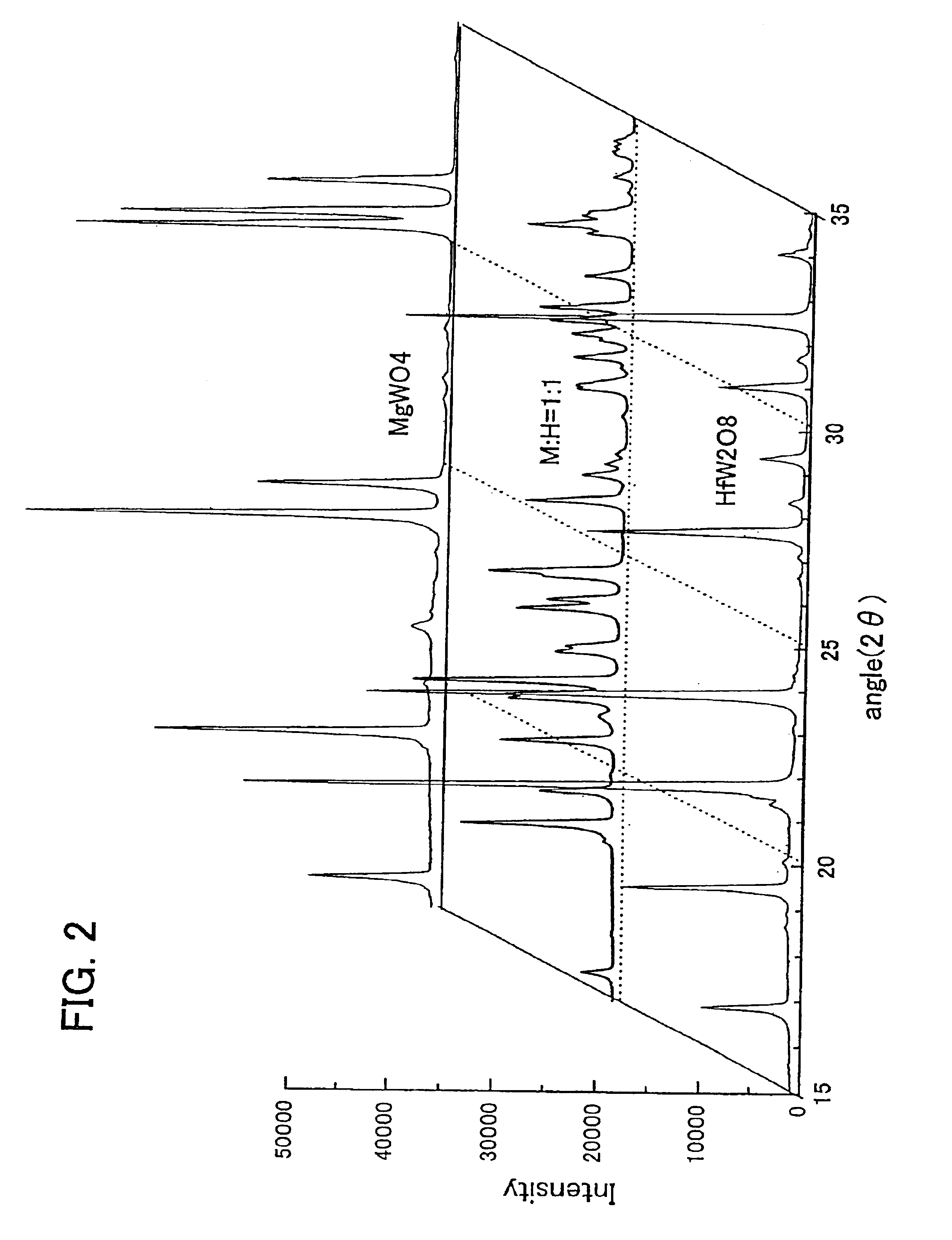
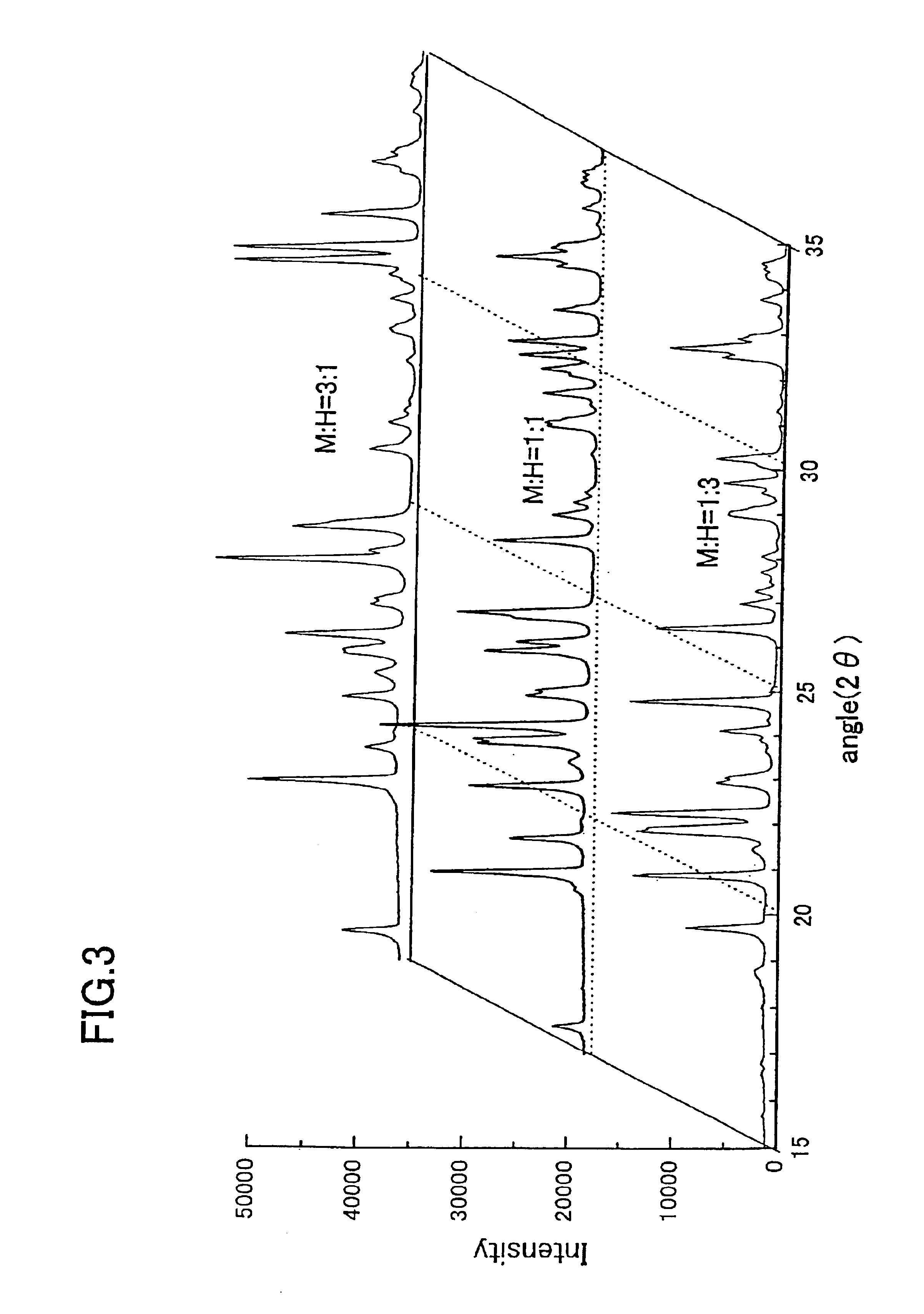
In this embodiment of the present invention, shown is a case in which a zero thermal expansion material is produced using a material containing the double oxide represented by the chemical formula: (RM)(QO4)3 (wherein R is Zr, Hf or a tetravalent metallic element represented by a mixture system of these, M is Mg, Ca, Sr, Ba, Ra or a divalent metallic element represented by a mixture system of these, and Q is a hexavalent metallic element selected from W and Mo). Materials used are a material A [A is a material having a crystal system of RQ2O2, and having a coefficient of thermal expansion which is negative (coefficient of thermal expansion: α(α>0); density: a] and a material B [B is a material having a crystal system of MQO4, and having a coefficient of thermal expansion which is positive (coefficient of thermal expansion: β; density: b]. Coefficients of thermal expansion of chief materials are shown in Table 1 below.

TABLE 1Coefficient ofDielectric constantthermal expansionMaterials...

embodiment 2

FIG. 4 is a perspective view showing a band-pass filter making use of the zero thermal expansion material, according to this Embodiment.

To the outset, using the calcined powders of HfW2O8 and MgWO4 weighed in a weight ratio of 1:1 as used in Embodiment 1, these were mixed together with a binder resin by means of a ball mill, and a green sheet was obtained from the resultant mixture by a doctor blade method. Then, the green sheet thus obtained was cut in a desired size, and twenty cut sheets were so piled up as to be 1 mm in plate thickness after firing, followed by compression molding. The molded product obtained was fired at 1,150° C. to obtain a platelike sintered body for a high-frequency circuit substrate. The coefficient of thermal expansion of this plate was measured to find that it was +0.8 ppm / ° C. Needless to say, the plate produced here contained the material of (HfMg) (WO4)3.

Next, as shown in FIG. 4, this platelike sintered body was used as a dielectric substrate 1 of a h...


PUM

PropertyMeasurementUnit
temperatureaaaaaaaaaa
densityaaaaaaaaaa
densityaaaaaaaaaa

Abstract

Using as a negative thermal expansion material a double oxide containing at least partly a compound represented by the chemical formula: RQ,O, (wherein R is Zr, Hf or a tetravalent metallic element represented by a mixture system of these, and Q is a hexavalent metallic element selected from W and Mo), and using as a positive thermal expansion material a material containing at least partly a compound represented by the chemical formula: MQX, (wherein M is Mg, Ca, Sr, Ba, Ra or a divalent metallic element represented by a mixture system of any of these, Q is a hexavalent metallic element selected from W and Mo, and X is an element selected from O and S), these are mixed preferably in a weight ratio of 1:1 and are synthesized to obtain a material whose coefficient of thermal expansion is substantially zero over a wide temperature range, i.e., a zero thermal expansion material. Using this zero thermal expansion material, high-precision and high-performance practical component parts can be obtained.

Description

BACKGROUND OF THE INVENTION1. Field of the InventionThis invention relates to a zero thermal expansion material and a practical component part making use of the same, which are used in electronic materials, precision machine component parts, structural materials and so forth of products making use of high frequencies.2. Description of the Prior ArtElectronic materials and structural materials have conventionally been produced using oxides and resins or using glass and metals. For example, substrates for high-frequency circuits have been produced using dielectrics or resins which have been made into sheets or plates. Such conventional electronic materials and structural materials usually have positive coefficients of thermal expansion. Hence, these materials have properties of causing expansion and contraction in accordance with rise and drop of ambient temperature.Meanwhile, in recent years, materials whose coefficients of thermal expansion are negative in some crystal systems are r...

Claims


Application Information

Patent Timeline
Patent Type & Authority Patents(United States)
IPC IPC(8): C04B35/486C04B35/053C04B35/495C04B35/488C04B35/03C01G39/00C01G49/00C01G41/00H01L23/12H01L23/15H05K1/03C04B35/00
CPCC01G39/00C01G39/006C01G41/006C01G49/00C04B35/053C04B35/488C04B35/495H01L23/15C01P2002/72H05K1/0306C01P2006/32C01P2006/10H01L2924/0002H01L2924/00
Inventor SUZUKI, TOMOKOOMOTE, ATSUSHIKUWATA, JUN
Owner PANASONIC CORP
Why Eureka
Try Eureka