Synthetic RF detection system and method

a detection system and synthetic technology, applied in direction finders, direction finders using radio waves, instruments, etc., can solve the problem of insufficient dynamic range for more sensitive problems

Inactive Publication Date: 2005-01-18
HONEYWELL INT INC
View PDF13 Cites 12 Cited by
  • Summary
  • Abstract
  • Description
  • Claims
  • Application Information

AI Technical Summary

Benefits of technology

The RF PIP employs two parallel down conversion line-ups with respective intermediate frequency (IF) signals being fed to independent parallel digitizers. Such a system enables simultaneous 2-channel processing. One of the RF PIP down converter line-ups includes a logarithmic radio frequency (RF) detector and a linear RF detector. With known or current equipment configurations only one of the detectors at a time can be routed via a switching circuit to a digitizer input. The present invention proposes to arrange the detectors and employ appropriate software techniques to effectively utilize both detectors simultaneously, thereby achieving the required 70 dB dynamic range.
In a second approach or embodiment, the conventional RF PIP down converter hardware configuration is modified to allow simultaneous routing of each detector into individual digitizers for parallel processing and reconstruction of the ON / OFF waveform. The modification includes rearranging the routing relays of the RF PIP such that simultaneous routing can be achieved. This method allows for measurement of s a single-shot or short pulsed RF signal with the aid of a trigger signal.

Problems solved by technology

However, this limited dynamic range is not sufficient for more sensitive testing / detecting that requires a full 70-dB instantaneous dynamic range, which is not uncommon on projects like RAH66.

Method used


Image

  • Synthetic RF detection system and method
  • Synthetic RF detection system and method
  • Synthetic RF detection system and method

Examples


first embodiment

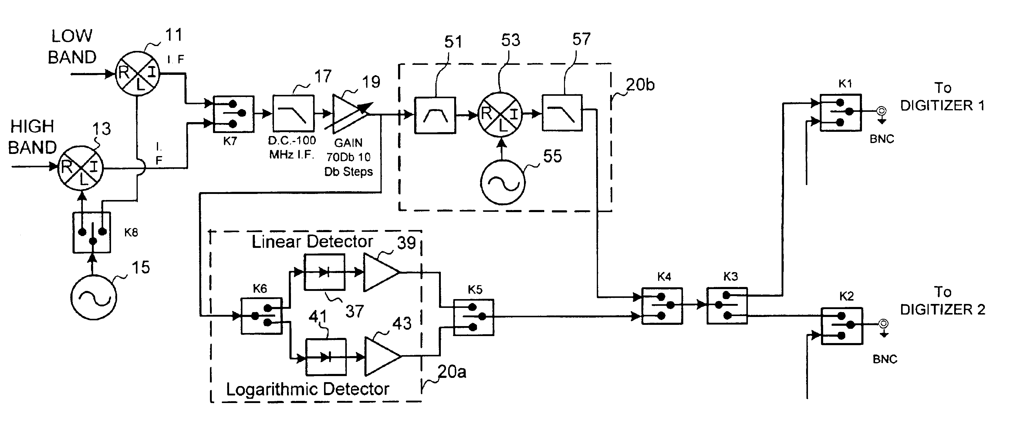
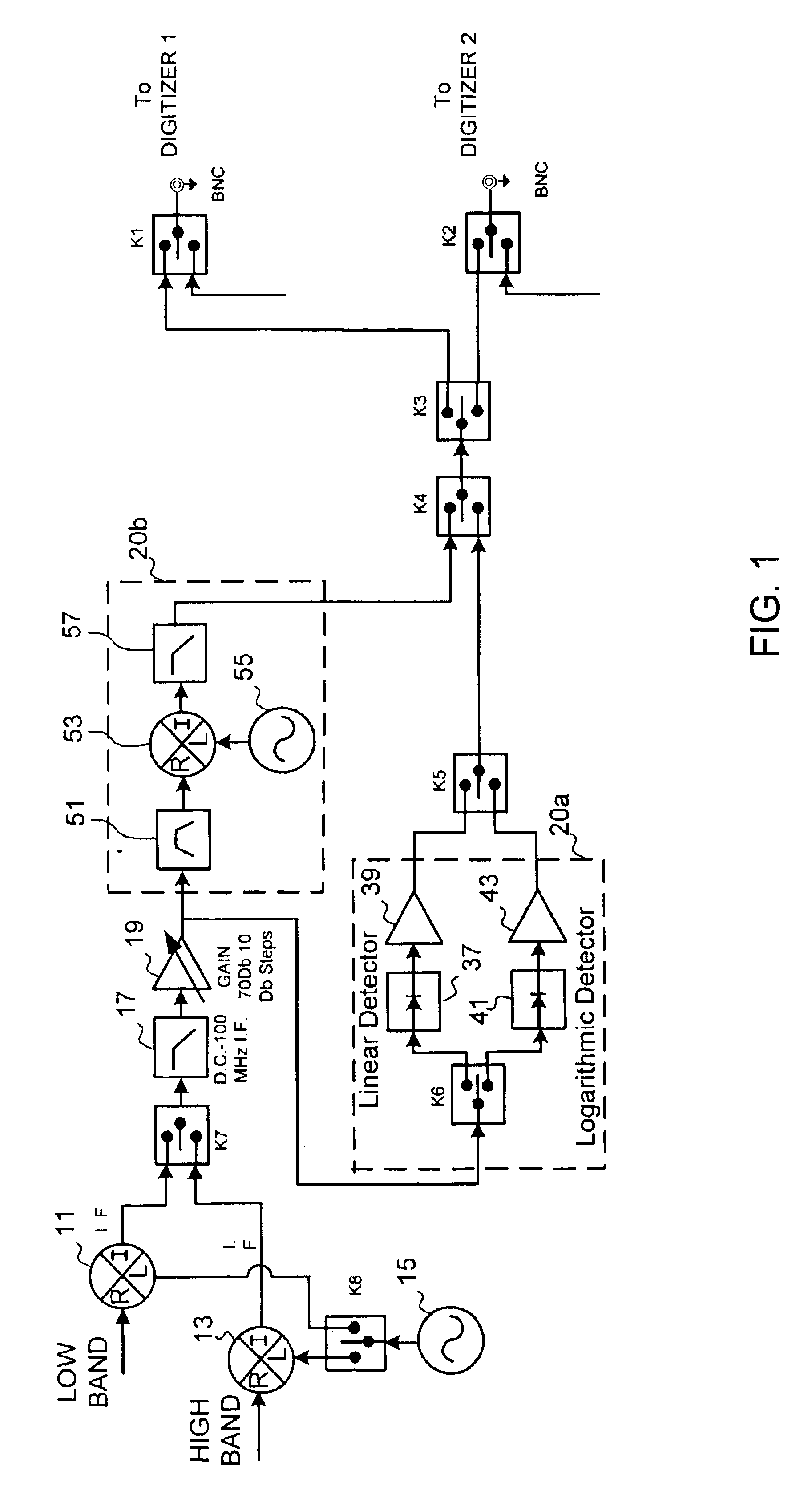
FIG. 1 illustrates a hardware configuration in accordance with a first embodiment of the present invention. As shown, mixers 11 and 13 receive low band and high band signals from a single input connector (not shown). The mixers are also fed a signal from source 15 (e.g., a local oscillator) via routing relay K8, which could also be a power divider or splitter. The resulting intermediate frequency signals output from mixers 11 or 13 are applied to routing relay K7, which preferably causes each of the outputted intermediate frequency signals to be multiplexed one at a time into a single digitizer (not shown) via routing relays K1 or K2 after passing through the additional circuitry, as described below

After passing through routing relay K7 the selected signal is passed through low pass filter 17 and a high gain amplifier 19. The output of high gain amplifier 19 is split such that the signal is passed through two different sets of circuit components designated by broken line boxes 20a a...

second embodiment

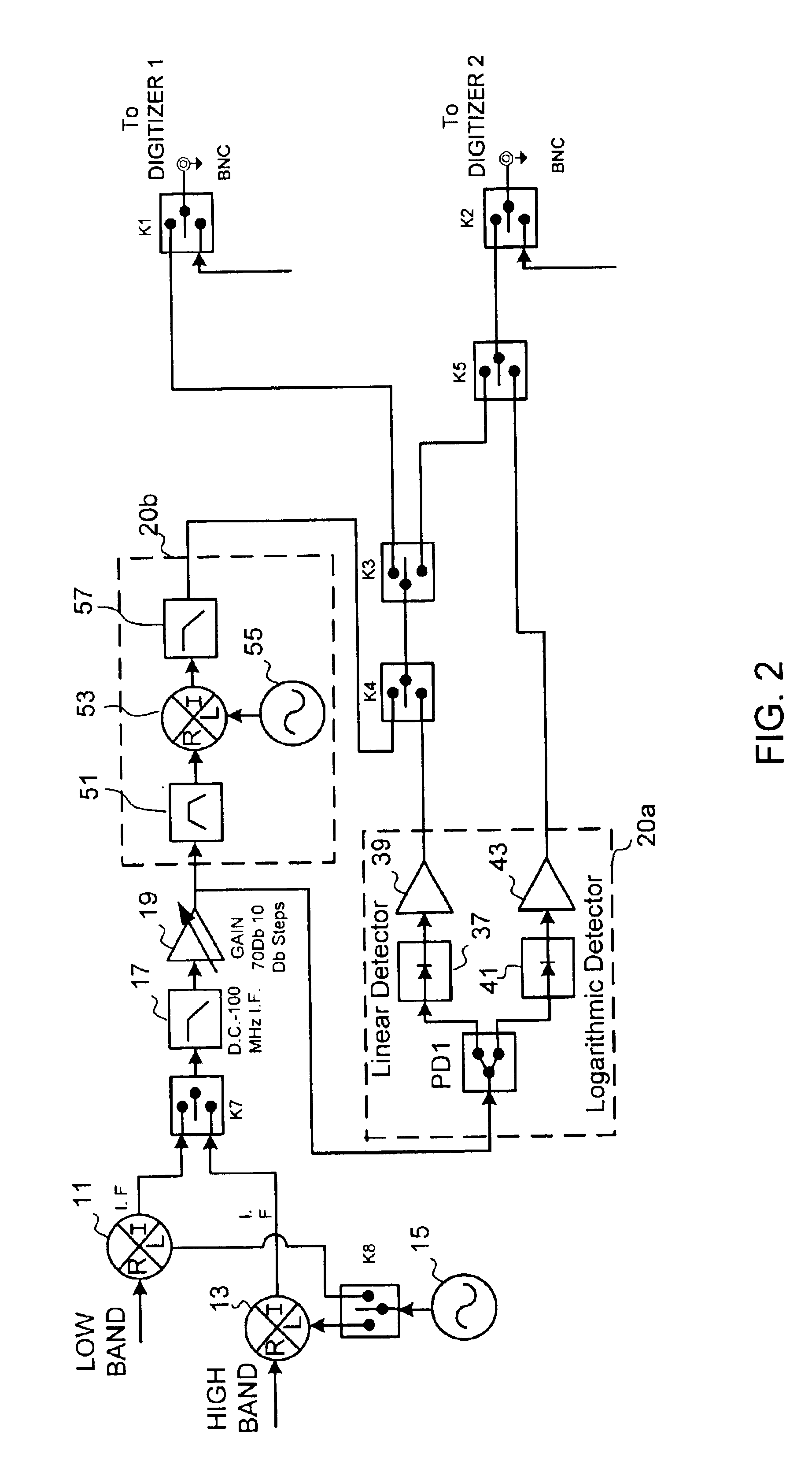
The configuration of the devices in the second embodiment is somewhat different from the first embodiment in that, as shown in FIG. 2, routing relay K5 is relocated to a position between routing relays K2 and K3. In accordance with this second embodiment it is possible to feed the outputs of both detectors 37 and 41 simultaneously to the inputs of independent digitizers that are connected to routing relays K1 and K2.

FIG. 3 depicts exemplary steps of a software algorithm, or process implemented in hardware, for implementing a synthesized RF detector by constructing a composite waveform in accordance with the present invention. In the first embodiment of the present invention, the process described below is performed after data from the linear and logarithmic detectors 37 and 41 has been digitized by the digitizers and recorded or stored. In the second embodiment, since both detectors can be monitored simultaneously by independent digitizers, the process shown in FIG. 3 can be perform...


PUM


Abstract

Outputs of a linear RF detector and a logarithmic RF detector are multiplexed individually to a single digitizer or simultaneously to a respective digitizers. A process generates a composite waveform from the resulting digitized data, either at a later time in the former case or in real-time in the latter case. To achieve simultaneous routing, several routing relays are arranged in a specialized configuration between the outputs of the RF detectors and the inputs of the digitizers.

Description

BACKGROUND1. Field of the InventionThe present invention is directed to radio frequency (RF) detection equipment arrangements and setups. More particularly, the present invention is directed to improved network analysis equipment configurations and methods for detecting pulsed RF signals.2. Background of the InventionIn some types of RF testing there is sometimes a need to measure / detect a pulse-modulated RF signal with relatively high ON-OFF ratios, e.g., greater than 70 dB, with a high RF level at the ON state. One example of such testing, which is conducted by the assignee of the present invention, takes place in conjunction with a project known as RAH66, the designation given to the U.S. Department of Defense's Comanche helicopter project. Some RF testing in this case employs a Radio Frequency Portable Maintenance Aid Instrumentation Pack, or RF PIP. The RF PIP is used as a field, or “flight-line,” test rig to test line replaceable units (LRUs) associated with different helicopt...

Claims


Application Information

Patent Timeline
IPC IPC(8): H04L27/06G01R29/08
CPCH04L27/06G01R29/06H04B1/10
Inventor HOFFMANN, SHLOMO
Owner HONEYWELL INT INC
Why Eureka
Try Eureka