Harmonic mitigating filter

a filter and harmonic technology, applied in the field of electric power distribution systems, can solve the problems of reducing the reliability of power distribution equipment, increasing the voltage total harmonic distortion level, and reducing the electromagnetic compatibility of loads, so as to achieve the effect of reducing harmonic curren

Inactive Publication Date: 2005-01-18
ABB (SCHWEIZ) AG
View PDF4 Cites 11 Cited by
  • Summary
  • Abstract
  • Description
  • Claims
  • Application Information

AI Technical Summary

Problems solved by technology

The harmonic currents create many problems in the power distribution system, including increased voltage total harmonic distortion level, reduced electromagnetic compatibility of the loads, reduced reliability of the power distribution equipment, increased power losses, reduced power factor, and other problems which are well known to those skilled in the art.
As is well known power factor corrected power supplies are expensive and have a limited application; active filters have a high cost, poor reliability and poor dynamic characteristics and may not be practical for use with large ASDs; resonant L-C filters have a high cost, poor effectiveness in low voltage systems and the tendency to cause the system to operate with a leading power factor; ac chokes have a high voltage drop across the reactors; and phase shifting systems are typically limited in the number of harmonic orders which can be mitigated and the degree of harmonic mitigation depends upon the extent to which harmonics produced by the various harmonic sources are identical and their phase shift angles.

Method used


Image

  • Harmonic mitigating filter
  • Harmonic mitigating filter
  • Harmonic mitigating filter

Examples


first embodiment

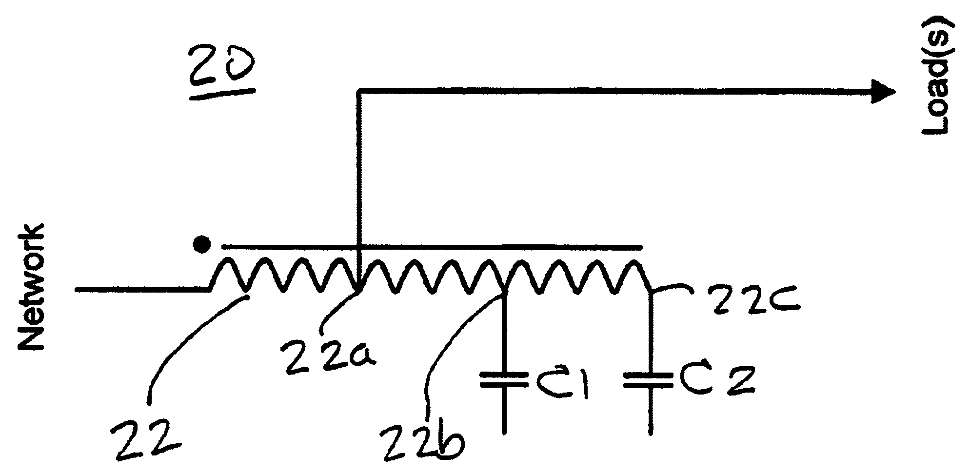
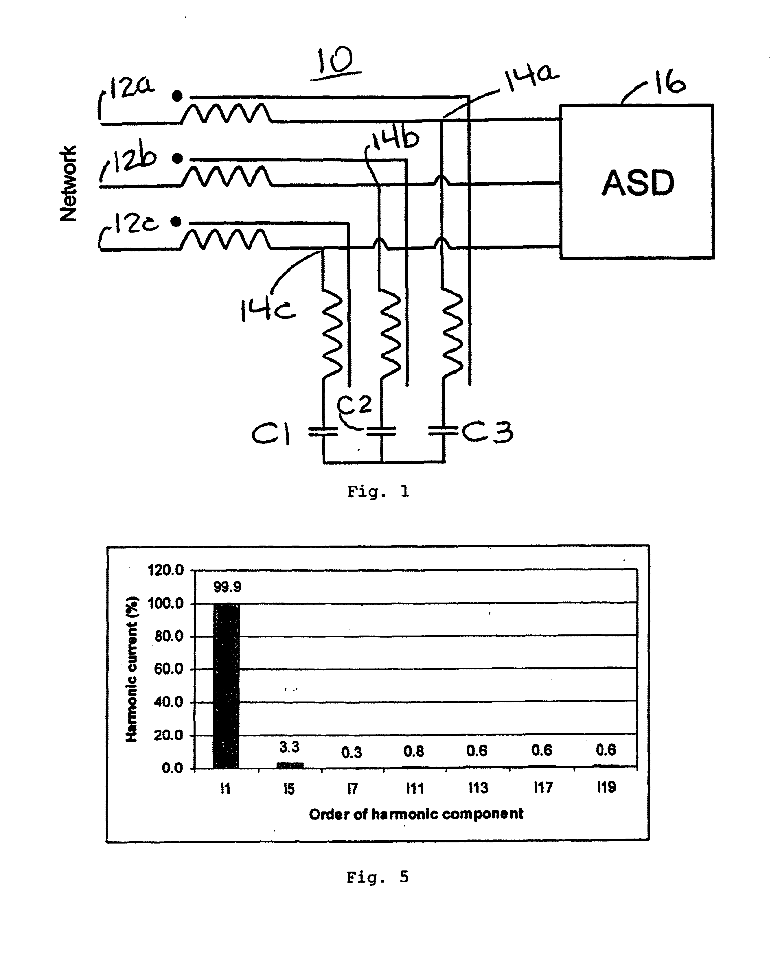
Referring now to FIG. 1, there is shown a first embodiment for the harmonic mitigation filter 10 for a three phase supply represented symbolically in FIG. 1 by the word “NETWORK”.

Filter 10 is connected between the three phase supply and a load 16 which may for example be an ASD as is shown in FIG. 1.

Filter 10 has one winding 12 with several terminals. The three phase supply is connected to the start 12a, 12b and 12c of the winding and capacitors C1, C2 and C3 are connected to the end of the winding in either a delta or a y-connection. There is one tapping 14a, 14b and 14c for the loads.

Referring to FIG. 5, there is shown the percentage of harmonic current versus the order of the harmonic component when the filter 10 is tested with selected inductances and capacitances for a VSD load. The total harmonic current distortion is less than 5%.

FIG. 2a shows for the harmonic mitigation filter 40 shown in FIG. 2 the connection of capacitors C1, C2 and C3 in the well known delta connection or...

embodiment 30

In the embodiment 30 there is also a single winding 32 that has three tappings 32a, 32b and 32c. The load is connected to tapping 32a, a capacitor C1 is connected to tapping 32b and a capacitor C2 is connected to tapping 32c. A third capacitor C3 is connected to the end 32d of the single winding 32.

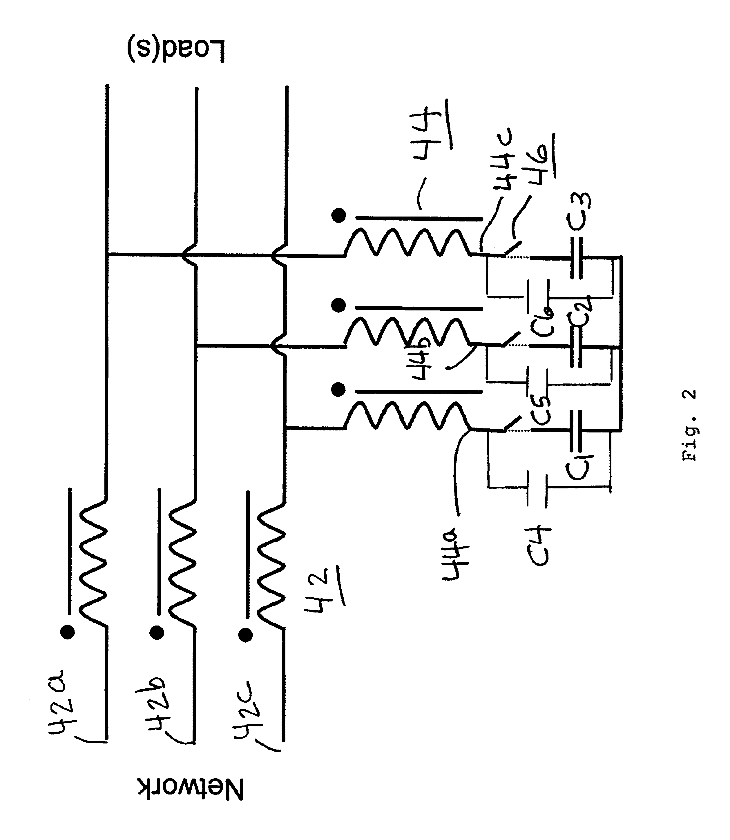
Referring now to FIG. 2 there is shown another embodiment for the harmonic mitigation filter 40 for a three phase supply (not shown). In this embodiment two or more separate reactors (windings) 42 and 44 are used to construct the harmonic mitigation filter of the present invention. The power supply is connected to the start 42a, 42b and 42c of winding 42. Capacitors C1, C2 and C3 are connected to end 44a, 44b and 44c of winding 44 in either a delta or a y-connection.

As an option a switch 46 can be connected between the windings ends 44a, 44b and 44c to when open isolate the capacitors C1, C2 and C3. In addition capacitors C4, C5 and C6 can be connected to the winding ends in parallel with...


PUM


Abstract

A filter for mitigating harmonics in an electrical distribution system. In one embodiment the filter has one winding that is connected to the power distribution system which may be a three phase system and capacitors are connected to other end of the winding in either a delta or y-connection. There is one tapping on the winding for connection to a load which may an adjustable speed drive. In another embodiment the filter has two or more separate reactors. In either embodiment a switch may be in series with the capacitors and capacitors may be connected in parallel with the series combination of switch and capacitors.

Description

FIELD OF THE INVENTIONThis invention relates to electrical power distribution systems and more particularly to filters for mitigating harmonics in such systems.DESCRIPTION OF THE PRIOR ARTElectrical distribution systems, for example for distributing an electrical power supply through a building or industrial facility, are often subjected to harmonic currents generated by non-linear loads such as electronic equipment (including computers, adjustable speed drives (ASD), uninterruptable power supplies (UPS), power rectifiers, etc.) and equipment that uses different kinds of arc processes (including arc discharge lighting systems). These harmonic-generating loads generate various levels of conventional harmonics (5th, 7th, 11th, 13th, 17th, 19th, 23rd, 25th etc.) and, for single phase line-to-neutral non-linear loads, also zero phase sequence or “triplen” harmonics (3rd, 9th etc.) in the power distribution system. The harmonic spectrum depends upon the nature of the harmonic-generating ...

Claims


Application Information

Patent Timeline
Patent Type & Authority Patents(United States)
IPC IPC(8): H02M1/12H02J3/01
CPCH02J3/01H02M1/126Y02E40/40
Inventor LAURI, PASI MATTI
Owner ABB (SCHWEIZ) AG
Why Eureka
Try Eureka