

Metal collector foil for electric double layer capacitor, method of producing the metal collector foil, and electric double layer capacitor using the metal collector foil
a technology of metal collector foil and electric double layer capacitor, which is applied in the direction of hybrid capacitor terminals, electrolytic capacitors, liquid electrolytic capacitors, etc., can solve the problems of deteriorating affecting the operation performance of rechargeable batteries, and relatively weak strength of the proposed electrode assembly, so as to achieve high operation performance of the capacitor and suppress the effect of age-related deterioration
- Summary
- Abstract
- Description
- Claims
- Application Information
AI Technical Summary
Benefits of technology
Problems solved by technology
Method used
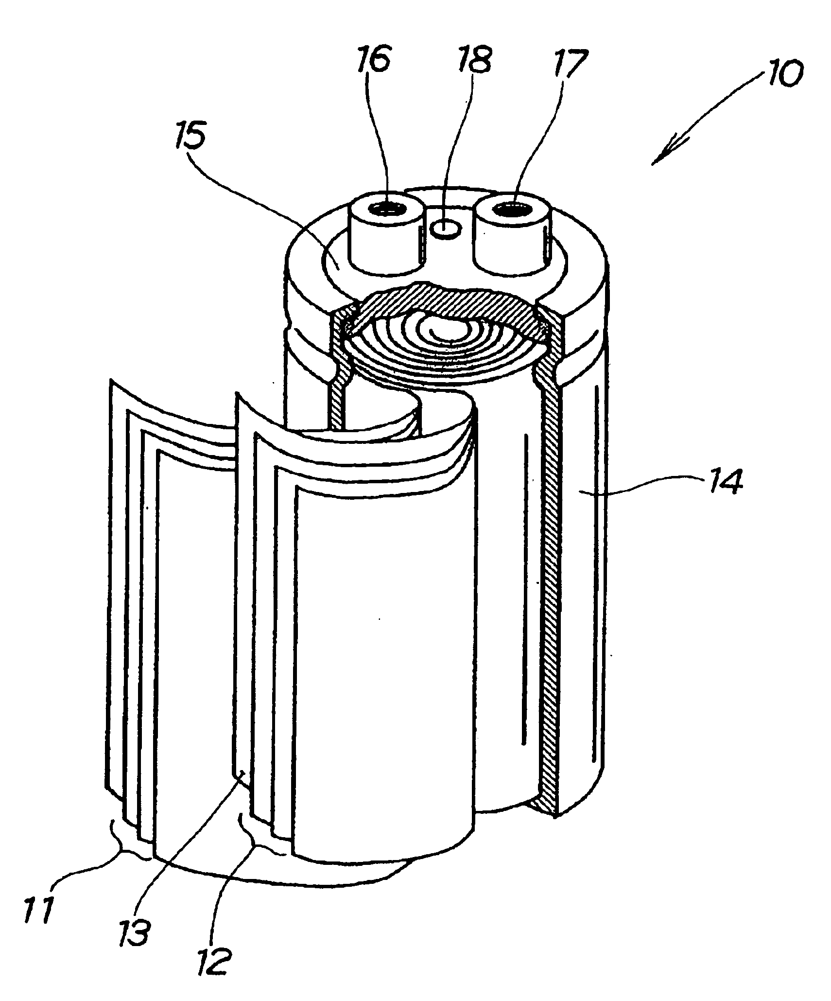
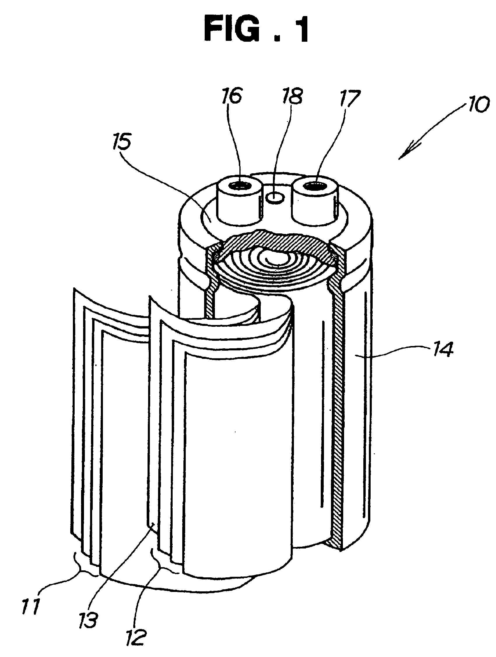
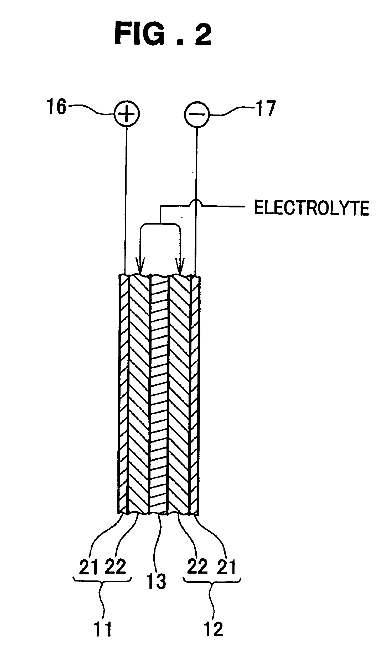
Image

Examples
second embodiment
For a more complete understanding, the present invention will now be described in greater detail with reference to the following examples.
EXAMPLES
For comparative purposes, eleven samples were prepared under the conditions given below.
1. Materials
1-1. Metal Collector Foil
A plain aluminum foil was etched at a temperature of 40 to 50° C. in a 5% hydrochloric acid solution with an AC current applied at 50 Hz with an electrolytic current density of 0.25 A / cm2 and the quantity of electricity 25 to 45 A·min / dm2. The temperature of the etching solution and the quantity of electricity were changed depending on Examples, as enumerated in Table 2 below.
The etched aluminum foil was removed from the etching bath and then washed at a temperature of 30-50° C. in a pH1 acid solution for 30 seconds or 60 seconds and subsequently dried with hot air heated at 180° C. The temperature of the washing solution and the washing time were set to change depending on Examples, as enumerated in Table 2.
TABLE 2T...
examples
For comparative purposes, twenty samples were prepared under the conditions given below.
1. Materials
1-1. Metal Collector Foil
1-1-1. Plain Aluminum Foil
Plain aluminum foils whose components are as shown in Table 4 were prepared were prepared as ordinarily-purified aluminum foils having purities below 99.8%.
TABLE 4Components (ppm)(%)CuNiZnSnFeAlExample 115—3—33599.647Example 223—2—32699.649Example 313112—34299.632Example 413172—34899.620Example 59—13—33199.647Example 611—18—34199.630Example 711—21431299.661Example 812—21934199.626Example 913—3—33199.653Example 1013—3—34199.643Comparative32—2—34399.623Example 1Comparative43—2—31299.643Example 2Comparative13223—34699.616Example 3Comparative9413—34399.604Example 4Comparative9—21—33399.637Example 5Comparative8—37—34499.611Example 6Comparative10—24334599.600Example 7Comparative9—25634999.584Example 8Comparative11—2—47699.511Example 9Comparative12—2—59399.393Example 10
As appears clear from Table 4 above, the plain aluminum foils each have a...
PUM
| Property | Measurement | Unit |
|---|---|---|
| tensile strength | aaaaa | aaaaa |
| temperature | aaaaa | aaaaa |
| current density | aaaaa | aaaaa |
Abstract
Description
Claims
Application Information