Infrared ray lamp, heating apparatus and method of producing the infrared ray lamp

a technology heating apparatus, which is applied in the field can solve the problems of abnormal power consumption increase, affecting the assembly work of infrared ray lamps, and difficulty in assembly work for them, so as to achieve high reliability, prevent fusing and breaking of heating portions, and increase power consumption.

Inactive Publication Date: 2005-01-18
PANASONIC CORP
View PDF34 Cites 27 Cited by
  • Summary
  • Abstract
  • Description
  • Claims
  • Application Information

AI Technical Summary

Benefits of technology

[0028]The present invention is intended to solve the above-mentioned problems and also intended to provide a highly reliable infrared ray lamp wherein its power consumption does not increase during use for a long time and its heating portions are prevented from fusing and breaking after use for a long time. The present invention is further intended to make the effect of the reduction of the reflectivity of an infrared ray reflection plate on the directional distrib

Problems solved by technology

A conventional infrared ray lamp causes a problem wherein its power consumption increases abnormally after use for a long time, and its heating portions fuse and break in some cases.
Furthermore, it is necessary to use a number of the tungsten supports for holding the tungsten spiral filament at the central portion of the glass tube, and the assembly work for them was not easy.
In particular, sealing the plural tungsten spiral filaments in the glass tube in order to obtain high output was very difficult.
The infrared ray lamps having the above-mentioned structures have good infrared ray emission rates, since their heating elements are formed of a carbon-based substance; but, there are the following problems.
The conventional infrared ray lamp therefore has the problem of abnormal heating at the connection portion.
Furthermore, if the temperature at the connection portion between the coil-shaped metal wire 102 and the metal foil sleeve 103 rises cont

Method used


Image

  • Infrared ray lamp, heating apparatus and method of producing the infrared ray lamp
  • Infrared ray lamp, heating apparatus and method of producing the infrared ray lamp
  • Infrared ray lamp, heating apparatus and method of producing the infrared ray lamp

Examples


sixth embodiment

[0088]FIG. 18 is a perspective view showing the positional relationship between the infrared ray lamp and the infrared ray reflection plate of a heating apparatus in accordance with the present invention;

seventh embodiment

[0089]FIG. 19 is a perspective view showing the positional relationship between the infrared ray lamp and the infrared ray reflection plate of a heating apparatus in accordance with the present invention;

[0090]FIGS. 20(a) and 20(b) is a partial view showing the structure of the lead wire taking-out portion of a conventional infrared ray lamp;

[0091]FIG. 21 is a partial view showing the structure of the lead wire taking-out portion of a conventional infrared ray lamp wherein two heating elements are sealed in a glass tube;

[0092]FIG. 22 is a plan view showing a conventional infrared ray lamp;

[0093]FIG. 23 is a perspective view showing the conventional infrared ray lamp;

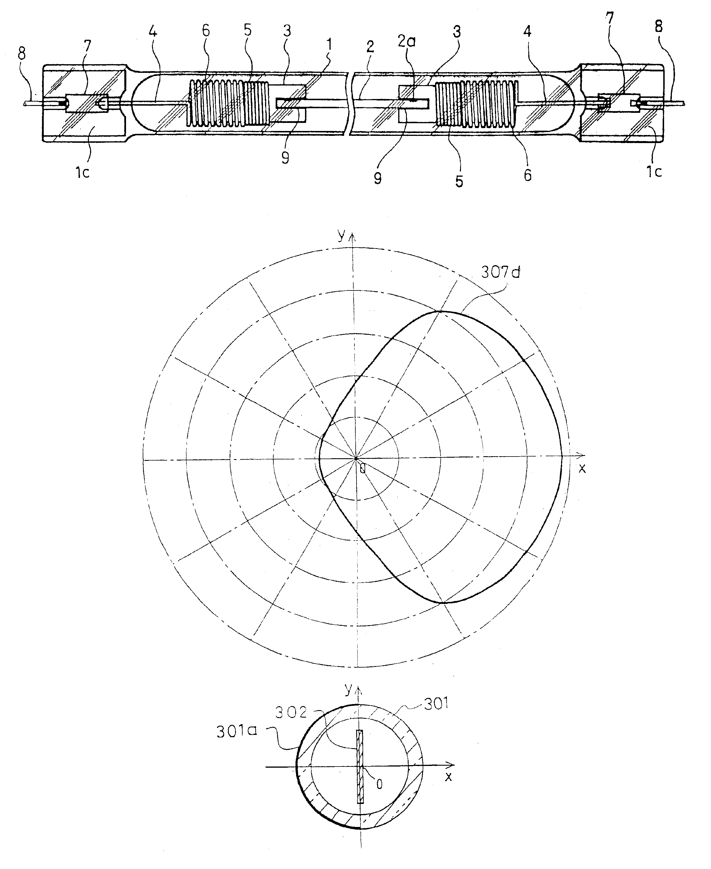
[0094]FIG. 24(a) is a graph showing the distribution curve of the intensity of the infrared rays emitted from the heating element of the conventional infrared ray lamp, and FIG. 24(b) shows the cross section of the central portion of the infrared ray lamp shown in FIG. 23;

[0095]FIG. 25 is a perspective view showing the p...

first embodiment

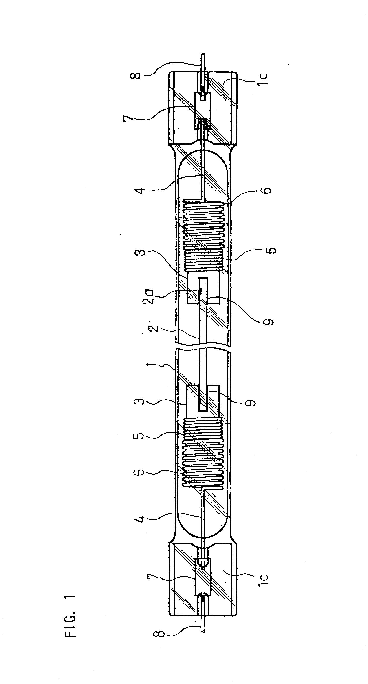
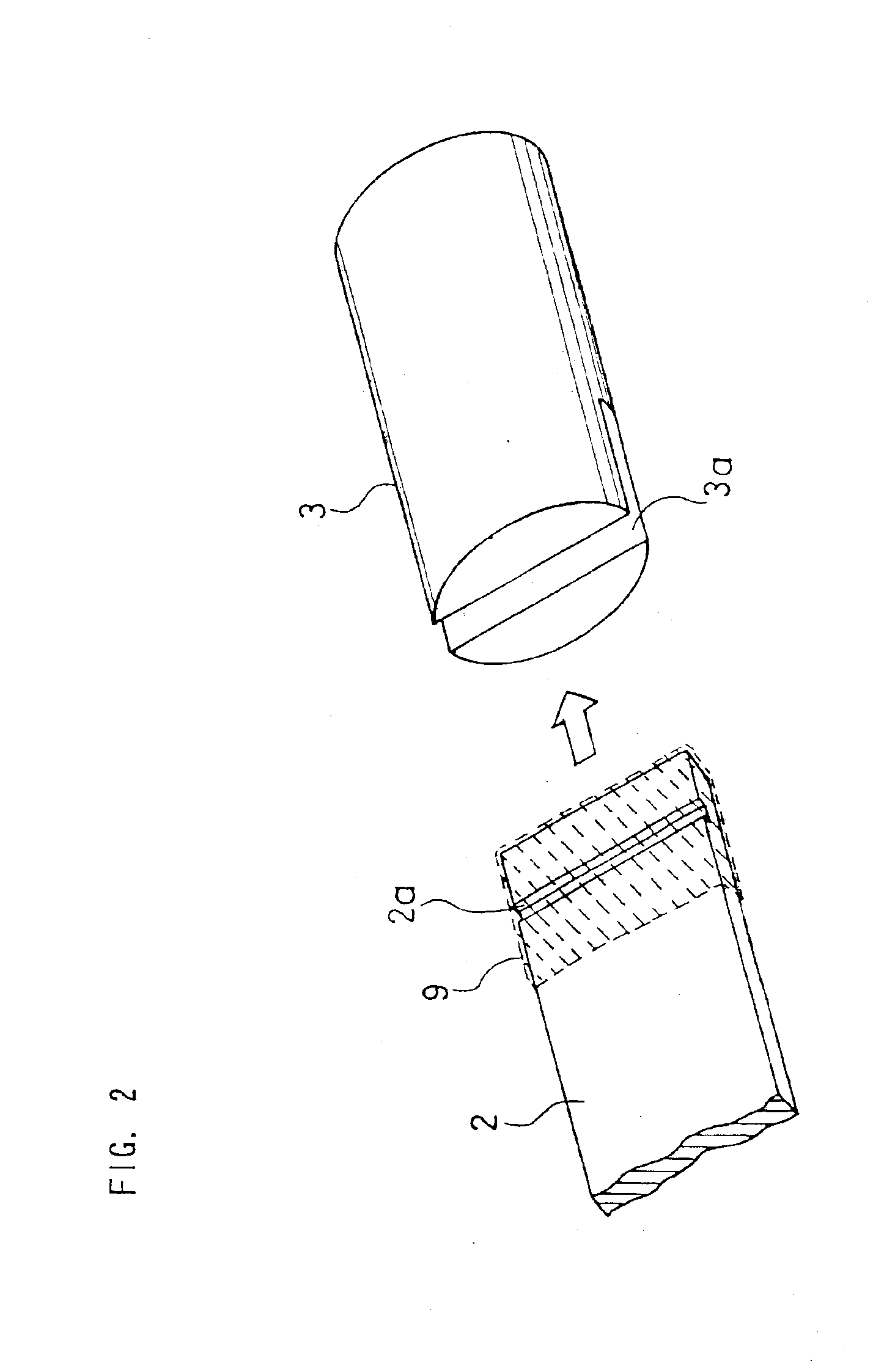
[0101]As shown in FIG. 1, in the infrared ray lamp of the first embodiment, a heating element 2, heat-emitting blocks 3 and internal lead wires 4 are sealed in a glass tube 1. The internal lead wire 4 is connected to an external lead wire 8 via a molybdenum foil sheet 7. The plate heating element 2 sealed in the glass tube 1 is formed of a carbon-based substance consisting of a mixture of crystallized carbon such as graphite, a resistance value adjustment substance and amorphous carbon. This heating element 2 has a plate shape measuring 6 mm in width, 0.5 mm in thickness and 300 mm in length for example. The heat-emitting block 3 is formed of a conductive material and electrically connected to one end of the heating element 2 by a method described later. A coil portion 5 is formed at one end of the internal lead wire 4, and a spring portion 6 having elasticity is formed following the coil portion 5.

[0102]As shown in FIG. 1, the coil portion 5 of the internal lead wire 4 is wound tig...


PUM


Abstract

An infrared ray lamp having a structure wherein a groove is formed in the vicinity of each of both end portions of a substantially plate heating element formed of a carbon-based substance, a carbon-based adhesive is applied to a region including the groove, and the end portion of the heating element is inserted into a slit formed at the end portion of a heat-emitting block having high conductivity so as to be sandwiched; by forming a reflection film on the glass tube of the infrared ray lamp, an infrared ray lamp having a desired emission intensity distribution is provided; a heating apparatus using this infrared ray lamp and method of producing the infrared ray lamp are also provided.

Description

TECHNICAL FIELD[0002]The present invention relates to an infrared ray lamp to be used for a heater for heating objects and a space heater for heating rooms, etc. (hereinafter referred to as a heating apparatus), more particularly to an infrared ray lamp having good functions as a heat source by using a carbon-based substance as a heating element, to a heating apparatus using the infrared ray lamp, and to a method of producing the infrared ray lamp.BACKGROUND ART[0003]A conventional infrared ray lamp causes a problem wherein its power consumption increases abnormally after use for a long time, and its heating portions fuse and break in some cases. This problem will be described below.[0004]As an infrared ray lamp conventionally used as a heat source, an infrared ray lamp having a tungsten spiral filament held at the central portion of a glass tube by a number of supports of tungsten is used. However, the infrared ray emission rate of the tungsten is so low as, 30 to 39%, and the rush...

Claims


Application Information

Patent Timeline
IPC IPC(8): H05B3/00
CPCH05B3/008H05B3/009H05B2203/032H05B3/00
Inventor KONISHI, MASANORI
Owner PANASONIC CORP
Why Eureka
Try Eureka