Structure for a polishing machine of an optical disk

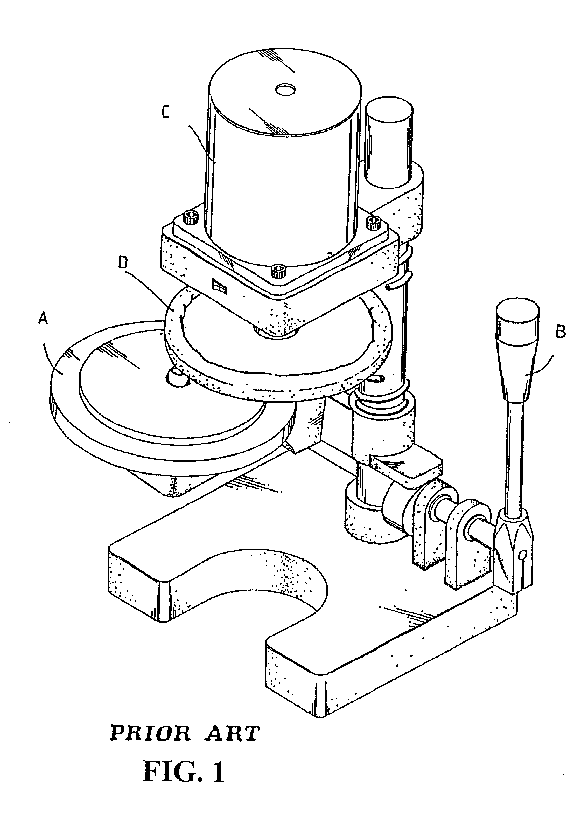
a technology of optical disk and structure, which is applied in the direction of optical surface grinding machines, edge grinding machines, manufacturing tools, etc., can solve the problems of plastic surface, easy to scratch the reading surface, time-consuming and laborious process, etc., and achieve the effect of improving the structure of the polishing machine, and improving the polishing

Inactive Publication Date: 2005-01-25
LIN MING SHENG
View PDF4 Cites 35 Cited by
  • Summary
  • Abstract
  • Description
  • Claims
  • Application Information

AI Technical Summary

Benefits of technology

The present invention is related to an improved structure for a polishing machine of an optical disk. The primary objective of the present invention is to provide a structure for a polishing machine with a precise polishing effect and higher automation to increase the quality of polishing.
The primary objective of the present invention is to provide a structure for a polishing machine which is simplified in structure, miniature in volume and easy to store and use.

Problems solved by technology

Since the reading surface of the optical disk is a transparent plastic surface without protective capability, it is easy to scratch the reading surface during moving and placing of the optical disk.
Contamination and scratches on the reading surface will affect the result negatively during the reading of the data, therefore it is necessary to perform a suitable cleaning process on the reading surface.
However, this process is time-consuming and requires some vigor, and does not have a good result.
Additionally, when there is over-wiping, or an abrasive paper and cloth is used in the cleaning process, more scratches will occur on the, plastic surface.
However, the abovementioned polishing machine for the optical disk possesses the following problems:1. The size of the prior art polishing machine is too large to be stored and carried.2. In order to ensure that the wiping range of the polishing pad covers the entire data zone of the optical disk, a bigger polishing pad, which increases the polishing time, is used.3. The polishing time can only be estimated approximately during the operating of the polishing machine, therefore over polishing commonly occurred and causes the optical disk to be damaged permanently while the polishing machine is being operated, therefore over-polishing often occurs causing permanent damage to the optical disk.

Method used


Image

  • Structure for a polishing machine of an optical disk
  • Structure for a polishing machine of an optical disk
  • Structure for a polishing machine of an optical disk

Examples


Embodiment Construction

The following descriptions are of exemplary embodiments only, and are not intended to limit the scope, applicability or configuration of the invention in any way. Rather, the following description provides a convenient illustration for implementing exemplary embodiments of the invention. Various changes to the described embodiments may be made in the function and arrangement of the elements described without departing from the scope of the invention as set forth in the appended claims.

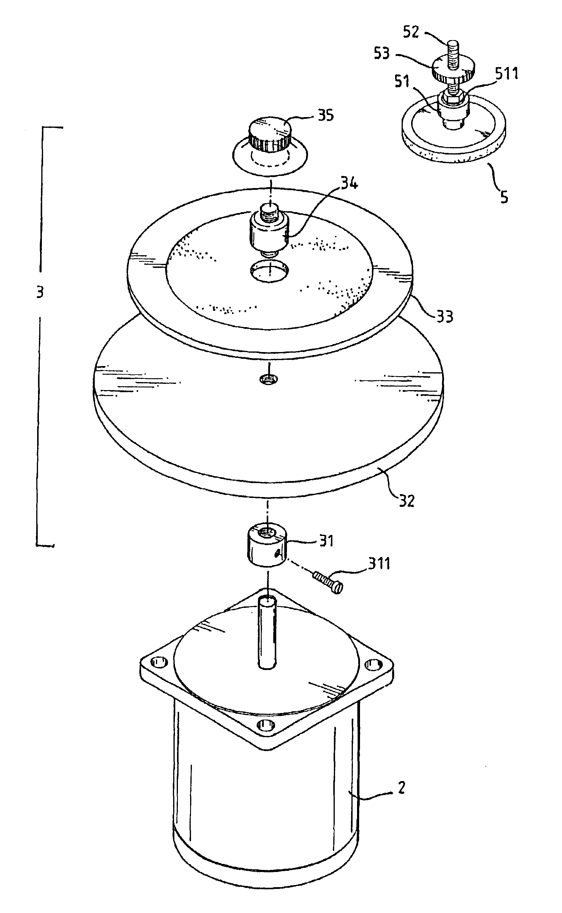
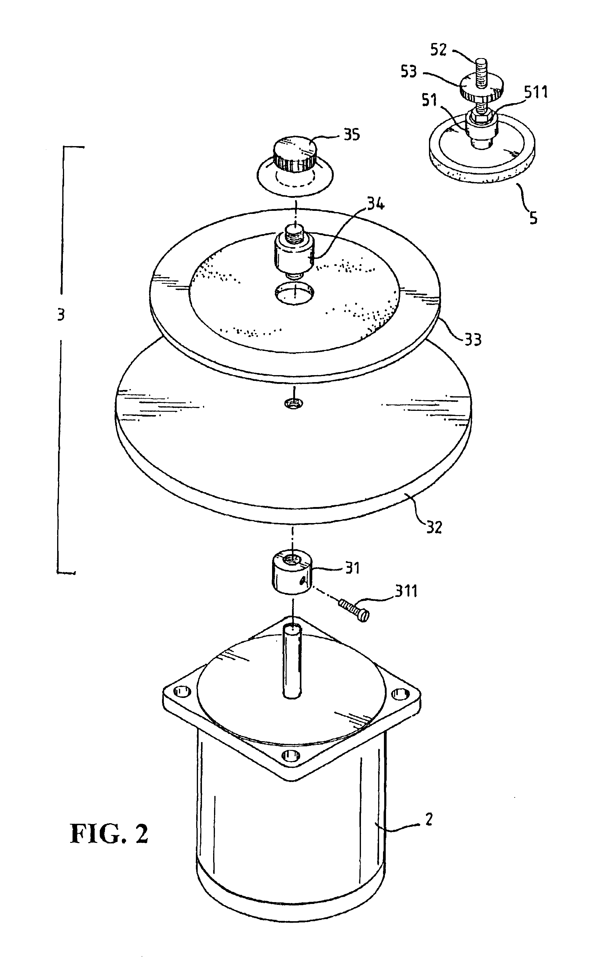
Please refer to FIG. 2 and FIG. 3. The present invention is related to an improved structure for a polishing machine of an optical disk, which comprises a motor (2), a turntable unit (3) integrated with a housing (1), at least two polishing wheels (5) positioned on a cover which can cover the housing (1), and a timer (6).

The motor (2) is fixed in the hollow housing with a predetermined strength, the turntable unit (3) is fixed at the front of the spindle of the motor, the turntable unit (3) comprises a...


PUM


Abstract

A structure for a polishing machine of an optical disk, which comprises a motor, a turntable unit integrated with a housing, at least two polishing wheel positioned on a cover which can cover up the housing, and a timer. When the cover is closed, the polishing wheel can polish the optical disk. The primary objective of this invention is to provide a structure for a polishing machine with a precise polishing effect and higher automation to increase the quality of polishing. The secondary objective of the present invention is to provide a structure for a polishing machine which is simplified in structure, miniaturize in volume and is easily stored and used.

Description

BACKGROUND OF THE INVENTION1. Field of the InventionThe present invention relates to an improved structure for a polishing machine, more particularly to an improved structure for a polishing machine of an optical disk with an enhanced efficiency.2. Description of the Prior ArtThe optical disk is widely used at present. Since the optical disk can be used to store large amounts of video data and digital data, it is commonly applied to such storage media as CD-ROM, Music-CD, VCD and DVD. In order to keep the optical disk in a better state of use, it is necessary to keep the reading surface of the optical disk smooth. Since the reading surface of the optical disk is a transparent plastic surface without protective capability, it is easy to scratch the reading surface during moving and placing of the optical disk. Contamination and scratches on the reading surface will affect the result negatively during the reading of the data, therefore it is necessary to perform a suitable cleaning pr...

Claims


Application Information

Patent Timeline
Patent Type & Authority Patents(United States)
IPC IPC(8): B24B13/00B24B27/00
CPCB24B27/0076B24B13/00
Inventor LIN, MING-SHENG
Owner LIN MING SHENG
Why Eureka
Try Eureka