
Apparatus and method for detachably securing a device to a natural heart

Inactive Publication Date: 2005-01-25
ABIOMED
View PDF59 Cites 69 Cited by
  • Summary
  • Abstract
  • Description
  • Claims
  • Application Information

AI Technical Summary

Benefits of technology

Methods and apparatus are disclosed for attaching cardiac devices onto a natural heart. The attachment methods and apparatus employ arrays of gripping elements, such as hooks or barbs, disposed on the surface of the devices. The gripping elements penetrate, and lodge themselves in, the epicardial tissue in order to secure the device to at least a portion of the surface of the heart muscle. The gripping elements secure the device to the surface of the heart, with limited depth penetration so as to avoid puncture of blood vessels or otherwise damaging or interfering with the function of the heart. The attachment mechanisms disclosed herein can also permit both attachment and detachment of device.

Problems solved by technology

These risks are heightened when the assist device includes blood-contacting surfaces.
Similar problems are encountered with passive cardiac assist devices, which have been proposed to prevent cardiac expansion beyond a predetermined volumetric limit in order to assist patients suffering from cardiac dilation or related conditions.
In the absence of such constraint, the weakened heart muscle will deteriorate and lose its ability to pump blood.
However, in certain disease states, the heart will increase in size over time beyond any normal volumetric range and then strain to pump blood.
One problem that limits the effectiveness of passive devices is the need for such devices to maintain a close fit about the heart.
Too loose a fit will degrade performance, while too tight a fit will put additional stress on the heart during diastolic expansion.
Conventional techniques and mechanisms for attachment of devices to the heart, such as sutures, glues, drawstrings and suction all have drawbacks, many of which directly contribute to the problems identified above.
Sutures and drawstrings, for example, loosen over time and exacerbate the problem of maintaining a close fit of the device to the heart.
Sutures can also cause trauma as a result of penetration into the myocardium.
Suction can likewise cause trauma (e.g., hematomas) while glues can make it difficult to detach the device from the heart.

Method used


Image

  • Apparatus and method for detachably securing a device to a natural heart
  • Apparatus and method for detachably securing a device to a natural heart
  • Apparatus and method for detachably securing a device to a natural heart

Examples


Embodiment Construction

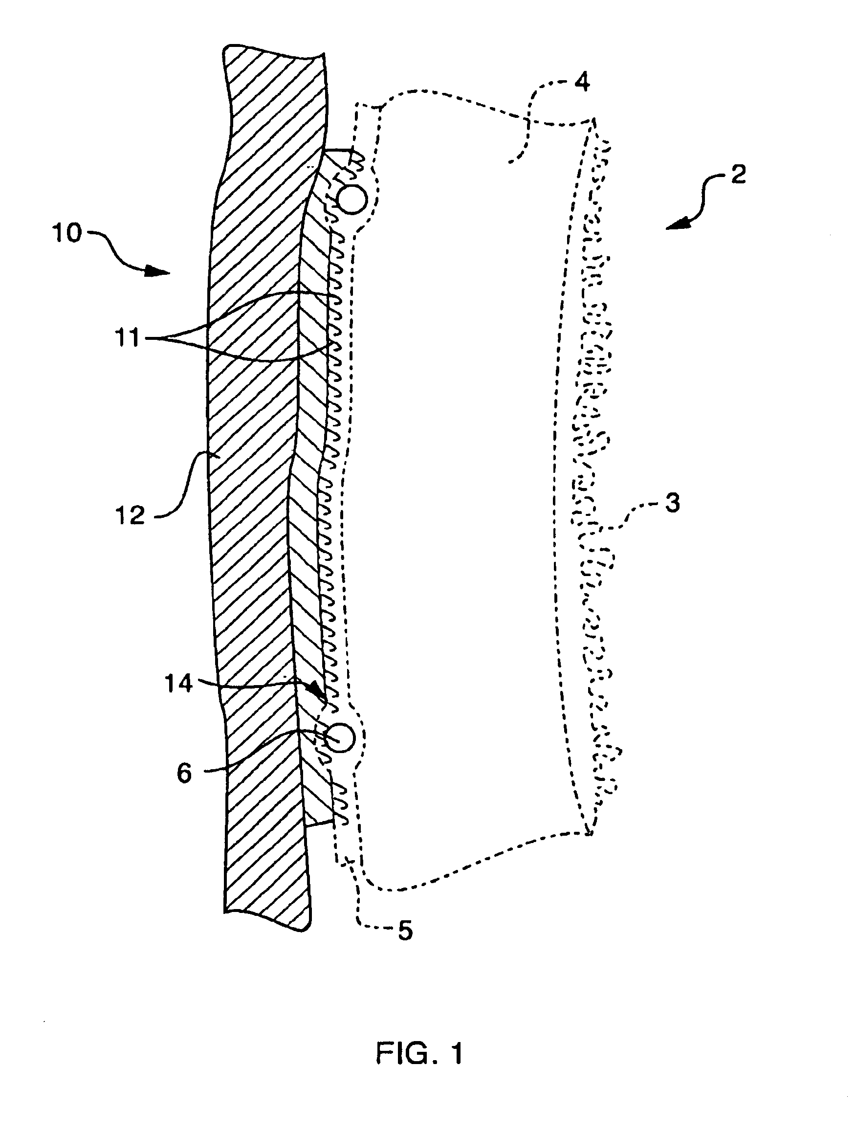
FIG. 1 provides a schematic illustration of the function of the gripping elements 11 according to the invention. As shown, an array 14 of gripping elements 11 is attached to the surface 12 of a cardiac device 10 and engaged in contact with the surface of the heart muscle 2. In this simplified cross-sectional view of the heart, only the endocardium 3, myocardium 4 and epicardium 5 are shown. The gripping elements are preferably designed to lodge themselves within the epicardium 5 and secure the heart to the inner surface of the cardiac device 10. Thus, the gripping elements preferably have limited depth penetration, e.g., penetrating only the serous pericardium—the visceral layers of the epicardium. As further shown in FIG. 1, the outer surface of the heart muscle 2 also includes blood vessels 6. Preferably, the gripping elements 11 are designed to avoid puncturing such blood vessels.

The term “gripping element” as used herein is intended to encompass any object capable of penetrating...


PUM


Abstract

Methods and apparatus are disclosed for attaching cardiac devices onto a natural heart by employing arrays of gripping elements, such as hooks or barbs. The gripping elements are designed to penetrate and lodge themselves in the epicardial tissue in order to secure the device to at least a portion of the surface of the heart muscle. The gripping elements, although designed to penetrate the surface of the heart, have limited depth penetration so as to avoid puncture of blood vessels. The attachment mechanisms disclosed herein can also permit both attachment and detachment of device.

Description

BACKGROUND OF THE INVENTIONThis invention relates to cardiac assistance devices and, more particularly, to devices designed to be secured to a natural heart for therapeutic or diagnostic purposes.A major consideration in the design of cardiac assistance systems is the risk of thromboembolism or infection. These risks are heightened when the assist device includes blood-contacting surfaces. To avoid the need for direct blood contact, a class of devices known as “extra-cardiac assist devices” has been proposed. Extra-cardiac devices typically are implantable within the thoracic cavity and surround at least a portion of the patient's heart to provide therapy without directly contacting the patient's circulatory system.A number of such implantable, extra-cardiac assist systems have been developed. These systems include active systems, which provide auxiliary pumping action to supplement or assist the blood pumping action of the natural heart, as well as passive systems, which support th...

Claims


Application Information

Patent Timeline
IPC IPC(8): A61H31/00A61B5/042
CPCA61B5/6882A61B5/042A61B5/283
Inventor MILBOCKER, MICHAEL T.STEWART, ROBERT B.BUCK, ROBERT L.
Owner ABIOMED
Learn More