
Electric start for a prime mover

a prime mover and electric start technology, applied in the direction of motor/generator/converter stopper, dynamo-electric converter control, turbine/propulsion engine ignition, etc., can solve the problem of fixed speed-torque profile of the motor, inability to adjust, severe reliability problems, etc., to achieve the effect of increasing the main field flux

Inactive Publication Date: 2005-01-25
HONEYWELL INT INC
View PDF8 Cites 48 Cited by
  • Summary
  • Abstract
  • Description
  • Claims
  • Application Information

AI Technical Summary

Benefits of technology

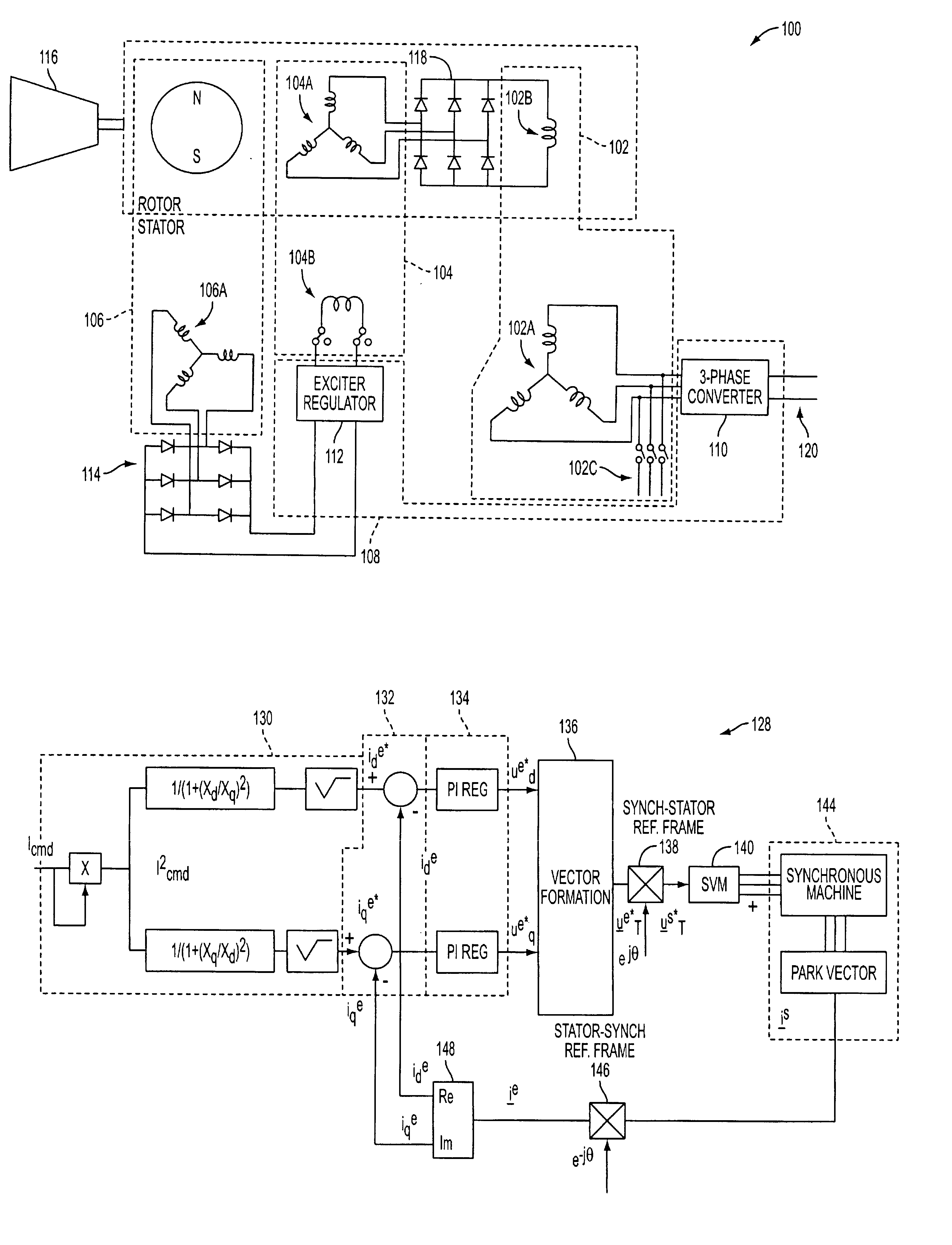
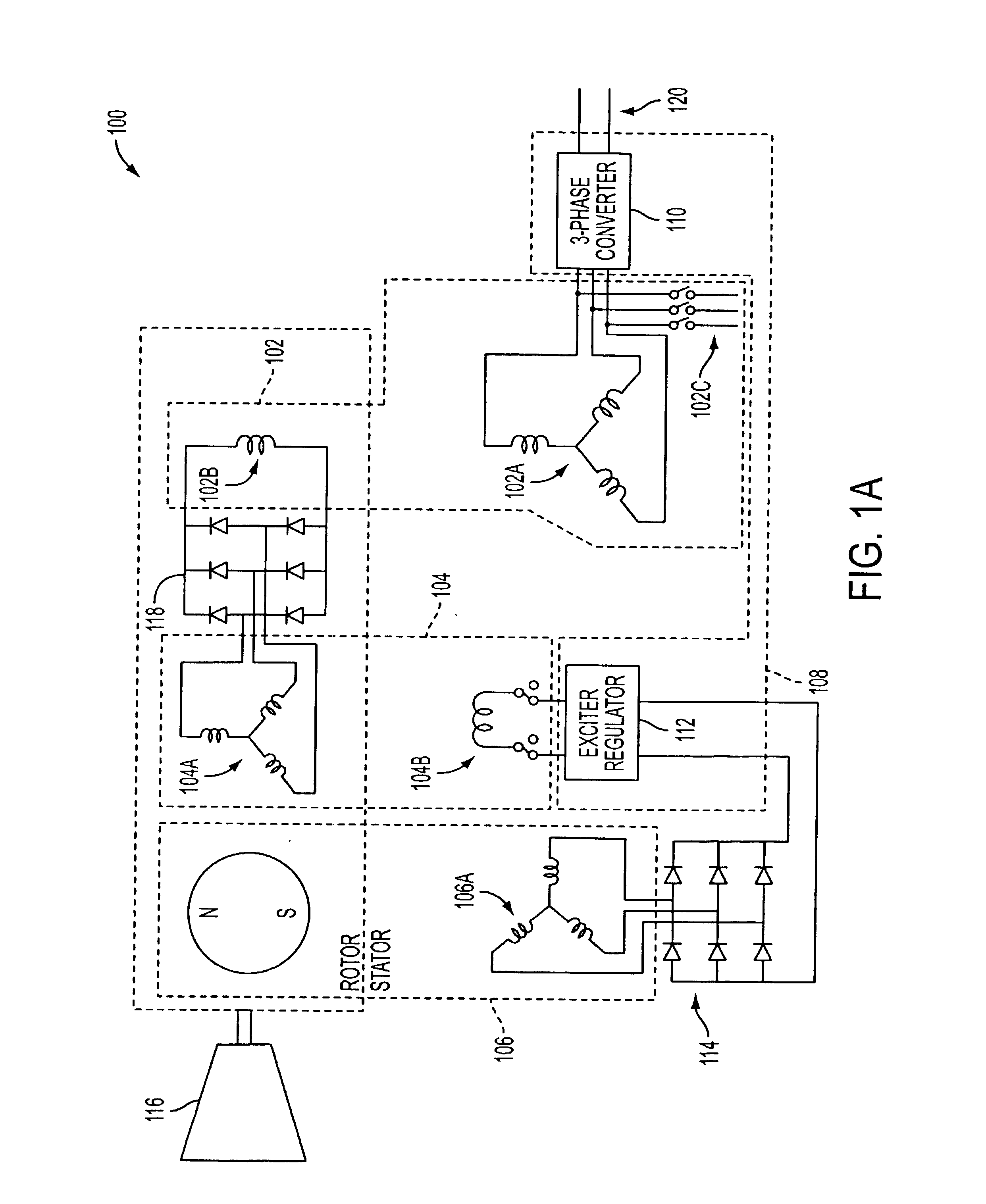
In another embodiment, the system uses the reluctance torque and additional reaction torque through DC field excitation of the exciter machine. Initially, at zero speed, DC current is applied to the field of the exciter, but zero voltage is induced in the rotor windings. As the speed of the machine increases, voltage is induced in the rotor of the exciter machine, which is applied via a rectifier mounted on the rotor as a DC voltage to the main machine field winding mounted on the rotating assembly. As speed increases, this applied voltage increases, increasing the main field flux.

Problems solved by technology

Such DC starter motors are of a type commonly referred to as brush type motors, and have severe reliability problems due to the brush-commutator interface that can deteriorate rapidly due to high altitude starts.
Further, the speed-torque profile of the motor is fixed and cannot be adjusted.
However, such systems are typically complex in their implementation, since main field flux must be provided at zero speed through the exciter machine and an associated inverter, and current in the main machine stator winding must be independently controlled via a second inverter to provide torque.

Method used


Image

  • Electric start for a prime mover
  • Electric start for a prime mover
  • Electric start for a prime mover

Examples


first embodiment

The present invention described below systematically uses either reluctance torque or a combination of both reluctance and reaction torque of a synchronous machine to minimize or optimize the required complexity of a starting system when applied to accelerate a prime mover, such as a gas turbine engine. In a first embodiment, only reluctance torque of the synchronous machine is used to accelerate the attached gas turbine. This embodiment would be preferred in applications where the reluctance torque is sufficient to cause “break-away” at zero speed and accelerate the gas turbine within a desired start time.

In a second embodiment of the present invention, starting the gas turbine initially uses reluctance torque only and at some point during start-up, DC field excitation is applied to the exciter stator winding of the synchronous machine. Although DC field excitation is typically applied at some point during start-up in the second embodiment, it can be applied at any time including d...


PUM


Abstract

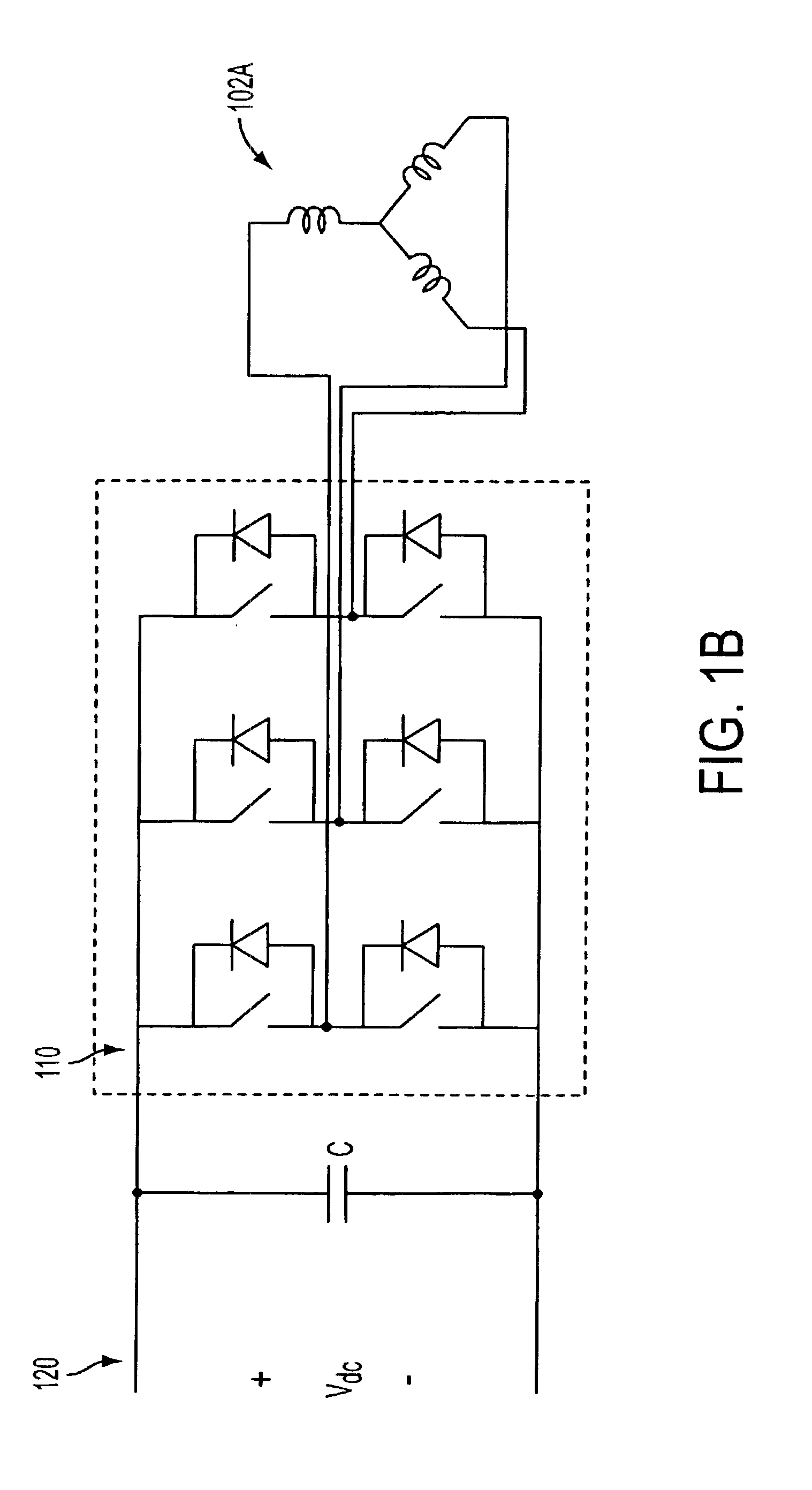
A system and method for using reluctance torque or a combination of both reluctance and reaction torque components of an attached synchronous machine (102) to accelerate a prime mover (116), such as a gas turbine engine, within a desired start time. The system selects a mode of starting operation, and thereafter applies reluctance torque through a synchronous machine (102) armature winding (102A) excitation as a single, sufficient starting force in a first mode, or staged reluctance and reaction torque through the additional excitation of the synchronous machine (102) field winding (102B) excitation in a second mode, using existing power electronics and controls.

Description

FIELD OF THE INVENTIONThe present invention relates to the start-up of prime movers in starter / generator systems, such as a gas turbine engine as used in aerospace applications. Specifically, the invention relates to a control system and method for using only the reluctance torque or combination of both reluctance and reaction torque of an attached synchronous machine to accelerate a prime mover within a desired start time.BACKGROUND OF THE INVENTIONIn a traditional system of starting a prime mover, such as a gas turbine engine, a starter motor is used to apply torque to the turbine engine's shaft for some period. As described in U.S. Pat. No. 6,035,626 issued to Wahl et al., the entire content of which being incorporated herein by reference, the gas turbine engine includes a compressor, a combustor, and a turbine. The compressor and the turbine are mounted for rotation on a shaft, which may also be used to drive other components, such as a gearbox and various accessories, such as a...

Claims


Application Information

Patent Timeline
IPC IPC(8): F02C7/26F02C7/268
CPCF02C7/268
Inventor SARLIOGLU, BULENTHUGGETT, COLIN E.
Owner HONEYWELL INT INC
Learn More