Magnetostatically coupled magnetic elements utilizing spin transfer and an MRAM device using the magnetic element

a magnetic element and magnetic element technology, applied in static storage, information storage, digital storage, etc., can solve the problems of increasing the area and complexity of b>20/b>, limiting the write current amplitude, and increasing the cross talk and power consumption. , to achieve the effect of reducing the current for writing, improving the function of the spin valve, and high readout signal

Inactive Publication Date: 2005-01-25
SAMSUNG SEMICON
View PDF8 Cites 339 Cited by
  • Summary
  • Abstract
  • Description
  • Claims
  • Application Information

AI Technical Summary

Benefits of technology

The present invention provides a method and system for providing a magnetic element capable of being written using spin-transfer effect and a magnetic memory using the magnetic element. In one aspect the method and system comprise providing a dual spin tunnel/valve structure and a spin valve structure. As used herein, the term “dual spin tunnel/valve structure”, different from spin tunnel junction, refers to a structure which incorporates a spin valve and a spin tunnel junction where the spin valve and the spin tunnel structure share a common free layer. The dual spin tunnel/valve structure includes a barrier layer between a first pinned layer and a first free layer, a second pinned layer and a first nonmagnetic spacer layer between the first free layer and the second pinned layer. The spin valve includes a second nonmagnetic spacer layer between a second free layer and a third pinned layer. The magnetic element is configured to allow the free layer magnetizations of the dual spin tunnel/valve structure and the spin valve structure be magnetostatically coupled and for at least one of the free layer magnetizations to change direction due to spin transfer when a write current is passed through the magnetic element. In one embodiment, a separation layer resides between the free ...

Problems solved by technology

This large current can cause a host of problems in the conventional magnetic memory 10.
For example, cross talk and power consumption would increase.
In addition, the driving circuits required to drive the current that generates the switching field at the desired me...

Method used


Image

  • Magnetostatically coupled magnetic elements utilizing spin transfer and an MRAM device using the magnetic element
  • Magnetostatically coupled magnetic elements utilizing spin transfer and an MRAM device using the magnetic element
  • Magnetostatically coupled magnetic elements utilizing spin transfer and an MRAM device using the magnetic element

Examples


second embodiment

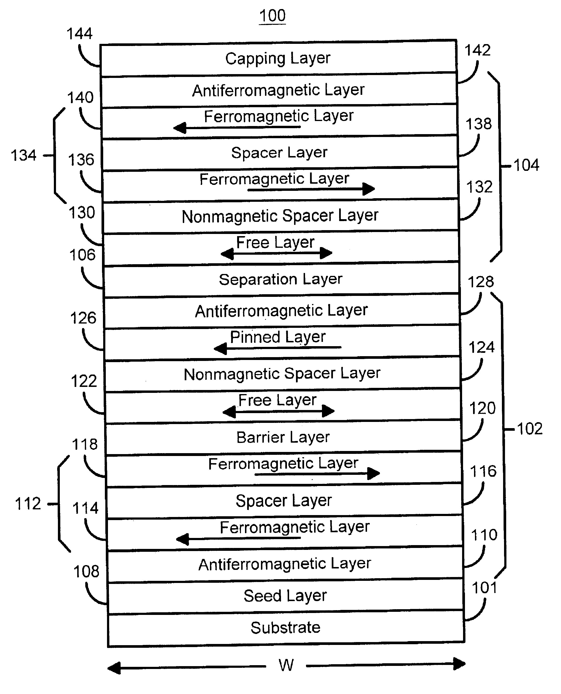
FIG. 4 is a diagram depicting a magnetic element 100′ in accordance with the present invention. The magnetic element 100′ has many of the same components as the magnetic element 100 depicted in FIG. 3. Consequently, analogous structures are labeled similarly for the magnetic element 100′ depicted in FIG. 4. In addition, these components are preferably fabricated in an analogous manner and made from similar materials as analogous components in the magnetic element 100. However, the spin valve is a dual spin valve 104′. In addition to the free layer 130′, the nonmagnetic spacer layer 132′, the pinned layer 134′, and the AFM layer 140′, the dual spin valve 104′ also includes a pinned layer 146 and a nonmagnetic spacer layer 148. In this embodiment the pinned layer 134′ is preferably a synthetic pinned layer including ferromagnetic layers 140′ and 136′ separated by a spacer layer 138′. Also In this embodiment the pinned layer 112′ is preferably a synthetic pinned layer including ferroma...

third embodiment

FIG. 5 is a diagram depicting a magnetic element 100″ in accordance with the present invention. The magnetic element 100″ has many of the same components as the magnetic element 100′ depicted in FIG. 4. Consequently, analogous structures are labeled similarly for the magnetic element 100″ depicted in FIG. 5. In addition, FIG. 5 also includes an additional dual spin valve 150. The second dual spin valve 150 includes a ferromagnetic pinned layer 152, a nonmagnetic spacer layer 160, a ferromagnetic free layer 162, another nonmagnetic spacer layer 164, a pinned layer 166 and an AFM layer 168. The nonmagnetic spacer layer 160 is preferably conductive and includes, but is not limited to, materials such as Cu. The pinned layer 152 is preferably a synthetic pinned layer including ferromagnetic layers 154 and 158 separated by a spacer layer 156. The materials used in the magnetic element 100″ are preferably the same as those used for analogous components of the magnetic element 100′ depicted...

fifth embodiment

FIG. 7 is a diagram depicting a magnetic element 200′ in accordance with the present invention. The magnetic element 200′ has many of the same components as the magnetic element 200′ depicted in FIG. 6. Consequently, analogous structures are labeled similarly for the magnetic element 200 depicted in FIG. 6. However, the dual spin valves 204′ and 208′ include synthetic pinned layers 234′ and 250′, respectively. The synthetic pinned layer 234′ includes ferromagnetic layers 252 and 256 separated by a spacer layer 254. The synthetic pinned layer 250′ includes ferromagnetic layers 258 and 262, separated by a spacer layer 260. The magnetic element 200′ thus functions in essentially the same manner as the magnetic element 200.

FIG. 8 is a diagram depicting a fifth embodiment of a magnetic element 200″ in accordance with the present invention. The magnetic element 200″ has many of the same components as the magnetic element 200″ depicted in FIG. 7. Consequently, analogous structures are labe...


PUM


Abstract

A method and system for providing a magnetic element and a corresponding memory are disclosed. In one aspect, the method and system include providing a dual spin tunnel/valve structure and at least one spin valve. The dual spin tunnel/valve structure includes a nonmagnetic spacer layer between a pinned layer and a free layer, another pinned layer and a barrier layer between the free layer and the other pinned layer. The free layers of the dual spin tunnel/valve structure and the spin valve are magnetostatically coupled. In one embodiment a separation layer resides between the dual spin tunnel/valve structure and the spin valve. In another aspect, the method and system include providing two dual spin valves, a spin tunneling junction there between and, in one embodiment, the separation layer. In both aspects, the magnetic element is configured to write to the free layers using spin transfer when a write current is passed through the magnetic element.

Description

FIELD OF THE INVENTIONThe present invention relates to magnetic memory systems, and more particularly to a method and system for providing an element that employs a spin transfer effect in switching and that can be used in a magnetic memory such as magnetic random access memory (“MRAM”).BACKGROUND OF THE INVENTIONMagnetic memories are often used in storing data. One type of memory element currently of interest utilizes magnetoresistance of a magnetic element for storing data. FIGS. 1A and 1B depict conventional magnetic elements 1 and 1′. The conventional magnetic element 1 is a spin valve 1 and includes a conventional antiferromagnetic layer 2, a conventional pinned layer 4, a conventional nonmagnetic spacer layer 6 and a conventional free layer 8. The conventional pinned layer 4 and the conventional free layer 8 are ferromagnetic. The conventional nonmagnetic spacer layer 6 is nonmagnetic. The conventional nonmagnetic spacer layer 6 is conductive. The antiferromagnetic layer 2 is ...

Claims


Application Information

Patent Timeline
IPC IPC(8): G11C11/16G11C11/02
CPCG11C11/16
Inventor ALBERT, FRANKHUAI, YIMINGNGUYEN, PAUL P.
Owner SAMSUNG SEMICON
Why Eureka
Try Eureka