Nanophase composite duct assembly

Inactive Publication Date: 2005-02-01
THE BOEING CO
View PDF38 Cites 20 Cited by
  • Summary
  • Abstract
  • Description
  • Claims
  • Application Information

AI Technical Summary

Benefits of technology

Generally, the nanophase aluminum alloy is synthesized by a powder processing sequence of cryogenic milling, out-gassing, and hot isostatic pressing (HIP) to form the billet. The billet is then extruded into a predetermined geometrical shape such as a cylindrical tube for use in many ducting applications for rocket engines. Further, in order to meet the dimensional requirements of rocket

Problems solved by technology

At the ambient or cryogenic temperatures of typical liquid propellant ducts, superalloys do not have an ideal high specific strength for the tubular section or an ideal high specific stiffness for the flange portion.
For example, when a superalloy tubular section has been designed with sufficient strength to accommodate propellant pressure, the associated stiffness is relatively high such that small misalignments of the flange portions results in high stresses therein after assembly of the duct.
Moreover, welding, weld inspection, and any rework necessary during assembly of high-pressure liquid ducts of the known art adds substantial cost to the rocket engine.
High strength aluminum alloys, although approximately one third the density of supe

Method used


Image

  • Nanophase composite duct assembly
  • Nanophase composite duct assembly
  • Nanophase composite duct assembly

Examples


Embodiment Construction

The following description of the preferred embodiments is merely exemplary in nature and is in no way intended to limit the invention, its application, or uses.

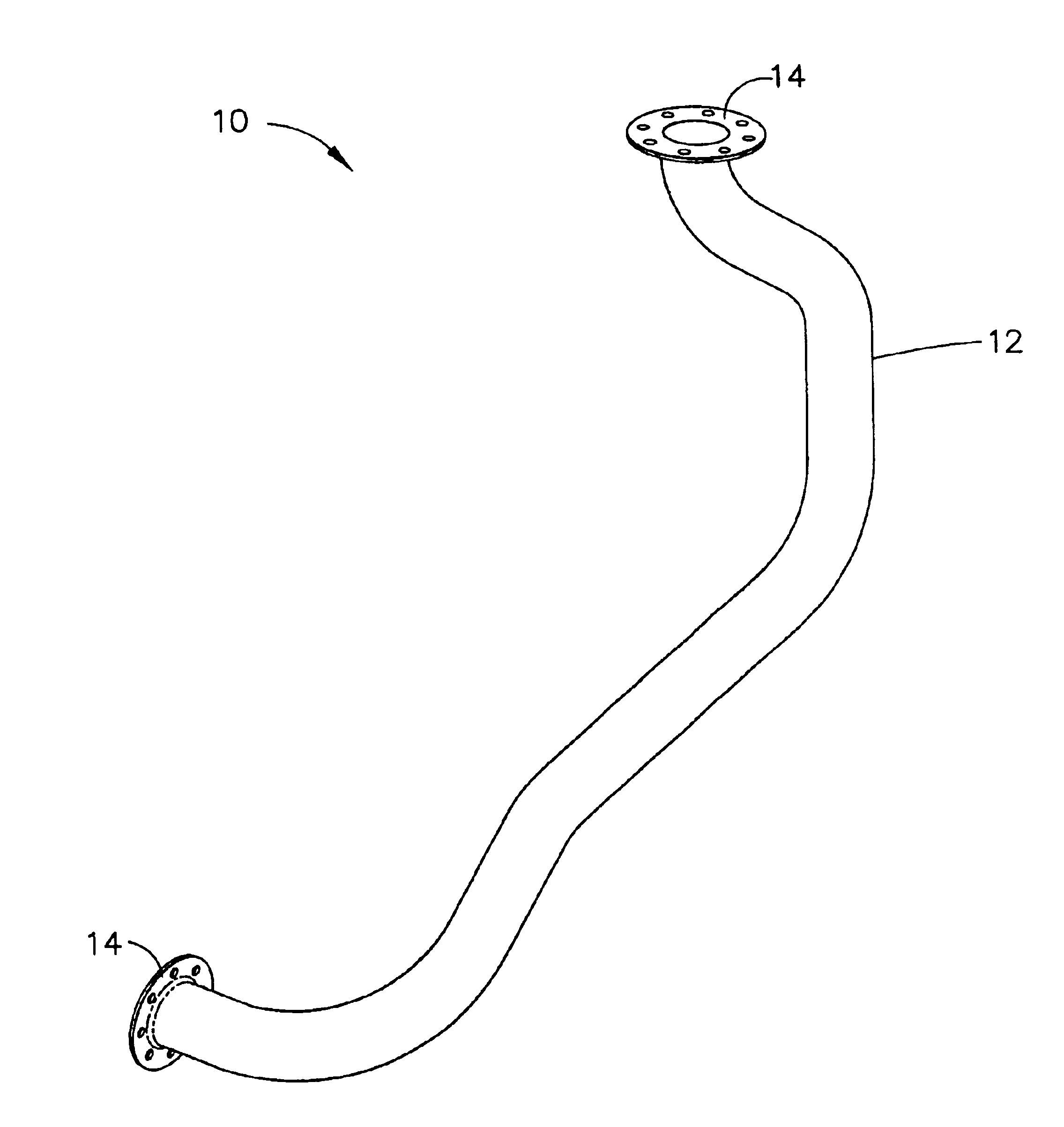
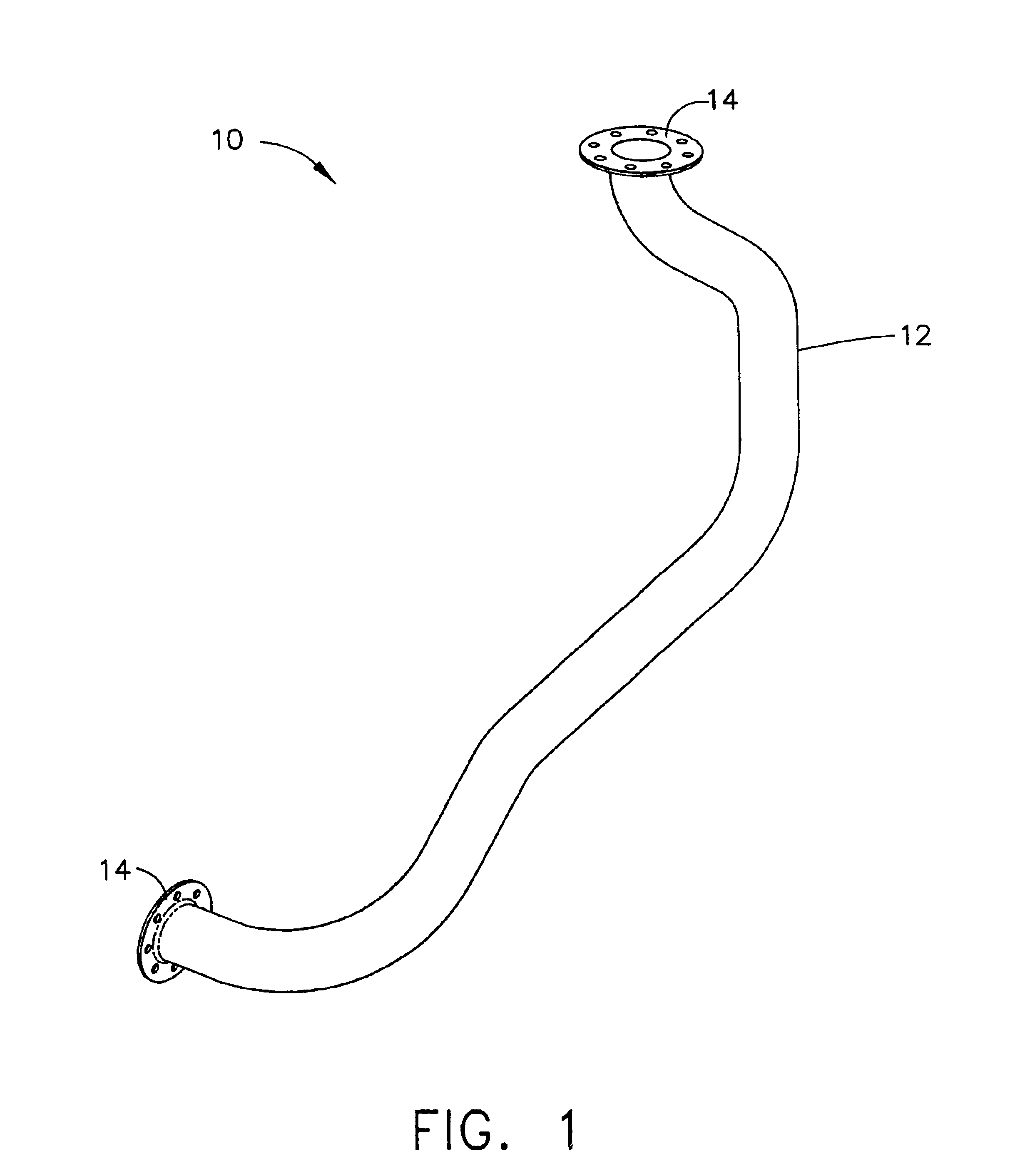
Referring to the drawings, a nanophase composite duct assembly according to the present invention is illustrated and generally indicated by reference numeral 10 in FIG. 1. As shown, the nanophase composite duct assembly 10 generally comprises a high-pressure liquid duct 12 joined to a high-pressure liquid ducting flange 14. Preferably, the high-pressure liquid duct 12 is an ultra-high strength nanophase aluminum alloy and the high-pressure liquid ducting flange 14 is formed from a ceramic particulate in a metal matrix, wherein the metal matrix is preferably aluminum. Accordingly, the nanophase composite duct assembly 10 provides significant weight and cost savings over superalloy high-pressure ducting of the known art.

The high-pressure liquid duct 12 is preferably formed by first synthesizing the nanophase aluminum alloy usin...


PUM

PropertyMeasurementUnit
Volumeaaaaaaaaaa
Volumeaaaaaaaaaa
Volumeaaaaaaaaaa

Abstract

A nanophase composite duct assembly and method of fabricating the same are provided that comprise an ultra-high strength nanophase aluminum alloy duct joined with a ceramic particulate reinforced metal matrix fitting, preferably using solid-state friction welding. The nanophase aluminum alloy duct is fabricated by extruding a billet formed by a process of cryogenic milling the alloy, followed by out-gassing, then hot isostatic pressing. The fitting is fabricated by combining a ceramic particulate with a metal matrix, preferably by powder processing or liquid metal infiltration. Further, the solid-state friction welding may comprise inertial welding, friction stir welding, or a combination thereof. As a result, a lightweight duct assembly is provided for high-pressure liquids such as propellants in rocket engines.

Description

FIELD OF THE INVENTIONThe present invention relates generally to high-pressure ducting and more particularly to high-pressure liquid ducting for propellants in rocket engines.BACKGROUND OF THE INVENTIONHigh-pressure liquid propellant ducts on rocket engines are generally heavy and can represent approximately 10-20 percent of the total weight of the engine. Generally, the ducts comprise a tubular section that is joined to a flange portion at each end thereof to form a section of high-pressure liquid ducting. The section of high-pressure liquid ducting is further joined to another section of ducting or to another component of the rocket engine such as a propellant feed tank or an inlet to the rocket engine of, for example, an aerospace vehicle.In the known art, high-pressure liquid propellant ducts are fabricated from nickel or iron-based superalloys such as 625 or 718, which have relatively high densities and thus contribute significantly to the weight of a rocket engine. To minimize...

Claims


Application Information

Patent Timeline
IPC IPC(8): B21C23/02B21C23/01B21C23/00B21C23/08B22F1/00B22F3/20F02C7/22F02K9/00F02K9/44B22F3/16B23K20/12C22F1/04
CPCB21C23/002B21C23/085B22F1/0044B22F3/162B22F3/20B23K20/12C22F1/04F02C7/222F02K9/44B21C23/01Y10T29/49346B22F2009/049B22F2998/00B22F2998/10B22F2999/00C22C2204/00Y10T29/49913Y10T29/4933B22F5/106B22F7/08C22C1/1036B22F9/04B22F3/15B22F2202/03B22F1/07
Inventor BAMPTON, CLIFFORD C.VAN DAAM, THOMAS J.MATEJCZYK, DANIEL E.
Owner THE BOEING CO
Why Eureka
Try Eureka