Most preferably, the magnet defines a
working space alongside of the poles, between the pole supports and between the poles and the connecting elements sufficient to accommodate one or more adult human attendants. Thus, an attendant can be positioned inside the
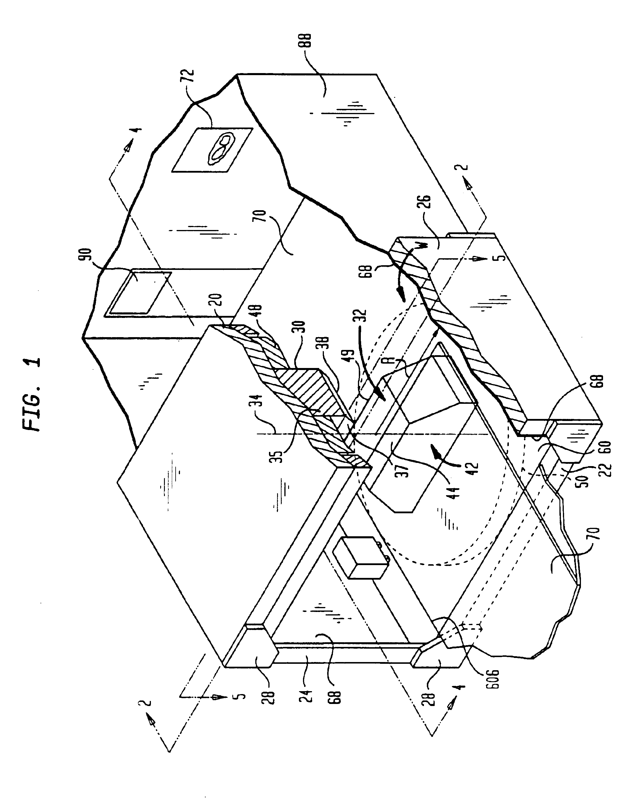
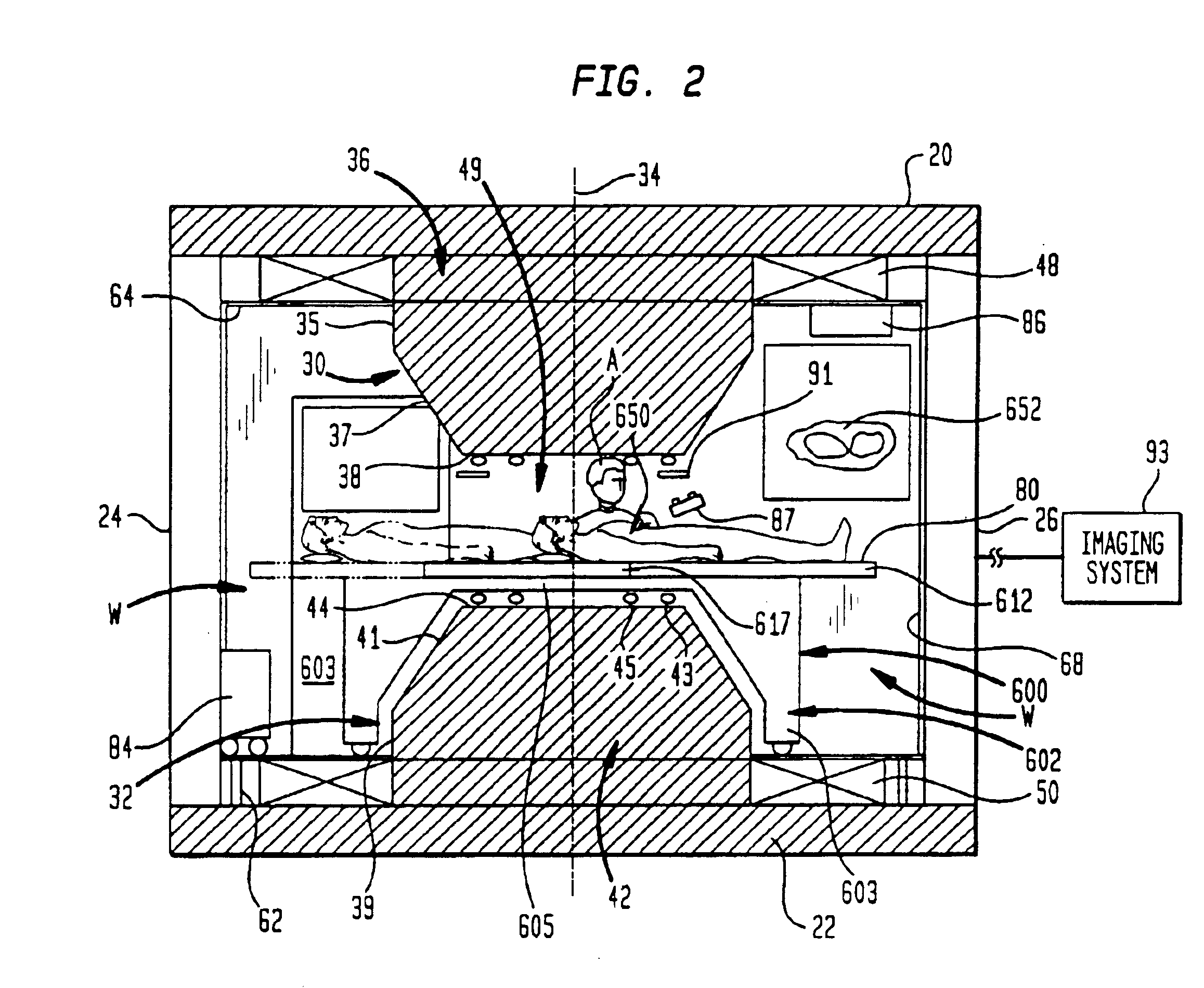
working space, within the magnet itself and can have access to a patient disposed in the gap between the poles. The working space desirably is about six feet or more high and about two feet or more wide, so that the attendant can work in a standing position. Most preferably, the working space extends entirely around the poles, and is unobstructed by any feature of the magnet itself. The magnet desirably includes a plurality of enclosing structures including walls, a floor and a ceiling which cooperatively define a room. The poles extend into the room, but the remainder of the frame desirably is at or outside the exterior of the room. For example, where the pole supports are spaced vertically apart from one another and the polar axis extends vertically, the poles project into the room from the floor and ceiling. Thus, the patient experiences entry into the MRI magnet as entry into a normal room with some structures extending from the floor and ceiling. Stated another way, the elements such as the connecting elements and pole supports are so far away from the patient that they do not create any feeling of
claustrophobia. Because the physician or other attendant is inside the room and inside the space enclosed by the pole supports and connecting elements, these elements do not impede access by the physician or other attendant to the patient at all.
The connecting elements may be in the form of plates constituting one or more walls of the room as well as providing the pole supports which may be formed as further plates constituting the floor and ceiling of the room. The enclosing structure may further include concealment structure which conceals those parts of the frame constituting the walls from view from within the room. For example, the interior surfaces of the plates may be covered with conventional wall, floor and ceiling coverings. This contributes to the patient's belief that he or she is inside a normal room. According to further aspects of the invention, the concealment structure may include surface decoration on the surfaces bounding the room as, for example, on the walls, ceiling or floor. The magnet structure may also include pole covers covering the poles and associated structure, and the surface decoration may be provided on the pole covers as well. The surface decoration may define an outdoor scene, such as a landscape or seascape incorporating a
sky region. This enhances the open, non-claustrophobic environment provided by the magnet.
The magnet desirably incorporates features to further enhance
field uniformity in the patient-receiving gap. Where coils are employed as the source of
magnetic flux, each coil encircles the associated pole. Also, the magnet desirably includes shimming features such as shim rings, slots or other elements defining
magnetic flux paths having different reluctances at different distances from the polar axis. To further promote
field uniformity, each pole may include a pole tip defining a distal end of the pole and a pole stem extending from the proximal end of the pole to the pole tip. The flux source is arranged to direct the flux in a forward direction through each pole. The magnet may include stem bucking magnets surrounding the pole stem. The stem bucking magnets desirably provide flux directed in a reversed direction opposite to the forward direction. This tends to minimize leakage of flux from the pole stems to the connecting elements. The relatively large spacing between the poles and the connecting elements in radial directions transverse to the polar axis helps to minimize flux leakage from the poles, so that a very large portion of the flux tends to pass between the poles. This further promotes flux uniformity and a
strong field in the subject-receiving gap.
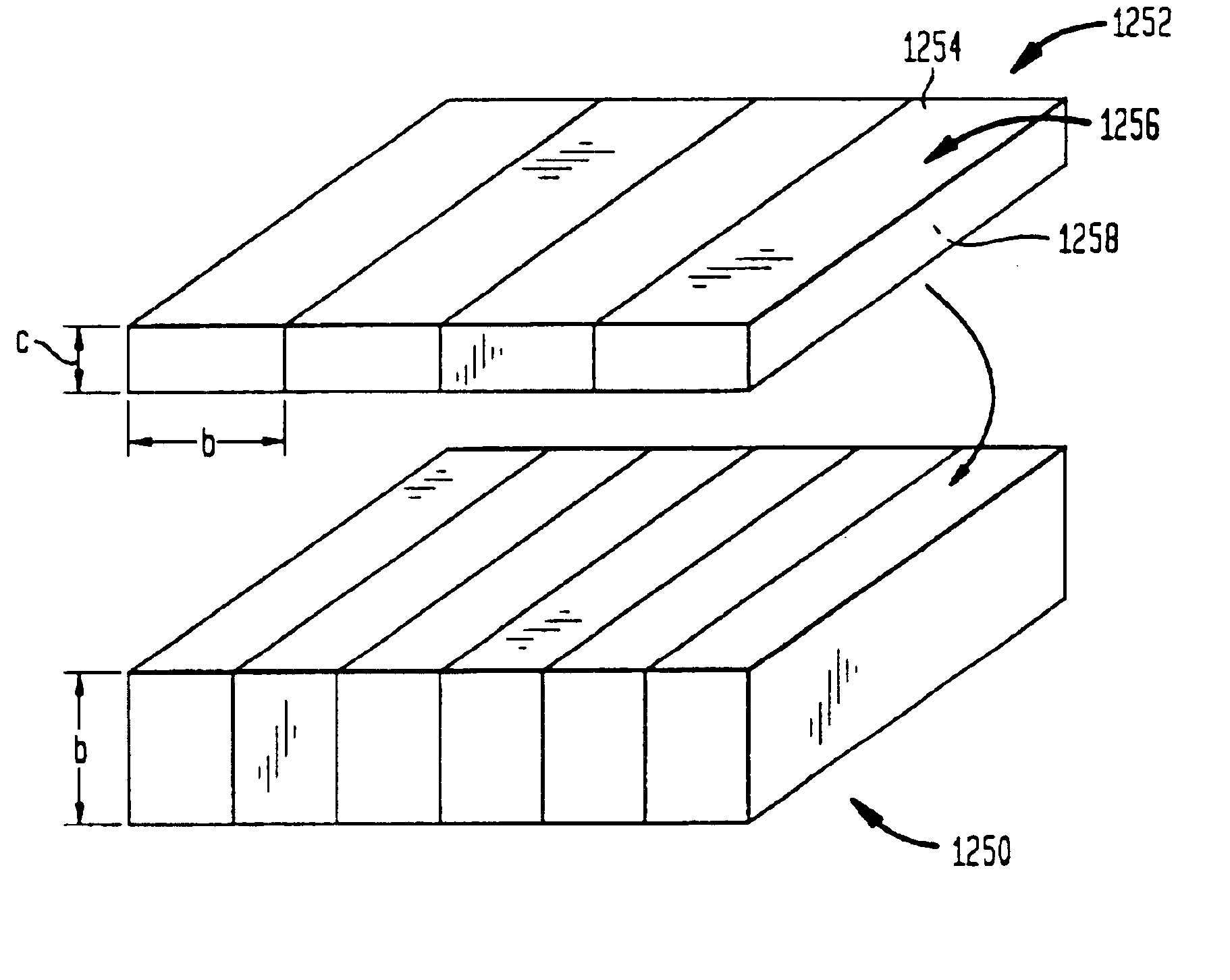
A further aspect of the invention provides improved resistive coils for
magnetic resonance imaging static field magnets. A coil according to this aspect of the invention includes a plurality of spiral windings extending around an axis. Each winding has an inner end adjacent the axis, an outer end remote from the axis and a conductor extending in multi-turn spiral between the inner end and the outer end. The windings include one or more outward windings and one or more inward windings. The turns of each outward winding are arranged such that a point moving along the turns in a first direction of rotation about the axis moves from the inner end towards the outer end. The turns of each inward winding are arranged so that a point moving along the turns in the first direction of rotation about the axis moves from the inner end towards the outer end. The windings are stacked one above the other along the axis and are electrically connected in series with one another. The electrical connections between the windings most preferably include one or more interior connections, the inner end of one of said inward windings being connected to the inner end of one of said outward windings at each such interior connection. The connections typically also include one or more exterior connections, the outer end of one of the outward windings being connected to the outer end of one of the inward windings at each such exterior connection. Most typically, the inward windings and the outward windings are arranged in alternating sequence along the axis. The interior connections and the exterior connections are also arranged in alternating sequence along said axis. As further discussed below, such a coil will provide essentially the same magnetic performance as a solenoid wound with an equal number of turns. However, the coil in accordance with this aspect of the invention can be fabricated more readily than a conventional
helical coil having multiple
helical layer nested within one another, particularly where the conductor is a relatively stiff element such as a metallic bar having cross-sectional dimensions of about 5 mm or more.
Preferably, the conductors of the windings are tubular so that each said winding has a bore extending through the conductor between its inner end and its outer end. The coil may further include a plurality of
coolant ports communicating with the bores of the windings. The ports serve as
coolant inlets and
coolant outlets for passing coolant through said windings. The coolant ports desirably are arranged so that the bore of each winding is connected in a fluid flow path between a coolant inlet and a coolant outlet, but so that each fluid flow path extends through less than all of said windings. Thus, different windings are connected in different fluid flow paths. Each fluid flow path provides flow resistance far less than that which would be expected in a single flow path extending through the entire coil. This greatly facilitates coil cooling, and minimizes
heat transfer to the pole and to other surrounding structures.
Yet another aspect of the invention provides a magnet for magnetic resonance imaging having a ferromagnetic frame defining a patient-receiving space and a source of
magnetic flux in
magnetic circuit with said frame so that flux produced by said source will pass through said patient-receiving space and through said frame; and means for suppressing temperature changes in the frame during operation. Most preferably, such means include
thermal insulation covering at least a part of said frame. This aspect of the invention incorporates the realization that changes in the magnetic properties of the frame due to changes in temperature of the frame can cause changes in magnetic fields in the patient-receiving space. By suppressing these temperature-induced changes, the magnet according to this aspect of the invention provides enhanced field stability and uniformity.

