
Industrial robot with a balancing device

Inactive Publication Date: 2005-02-01
ABB (SCHWEIZ) AG
View PDF8 Cites 17 Cited by
  • Summary
  • Abstract
  • Description
  • Claims
  • Application Information

AI Technical Summary

Benefits of technology

An industrial robot, comprising a manipulator with a control system, presents a robot foot, a stand and a robot arm with a wrist and a tool. The stand is pivotably arranged on the robot foot. The robot arm is pivotably arranged on the stand in a joint. The robot arm is composed of at least a first and a second arm part and also the wrist, all of which are pivotably arranged in relation to each other. A balancing arrangement is arranged to exert, when the robot is pivoted, a pulling force between a first and a second robot part and thereby to compensate for / balance the attraction of gravity when the relative position of the robot parts changes. The balancing arrangement is attached to the corresponding robot part with fastening devices.
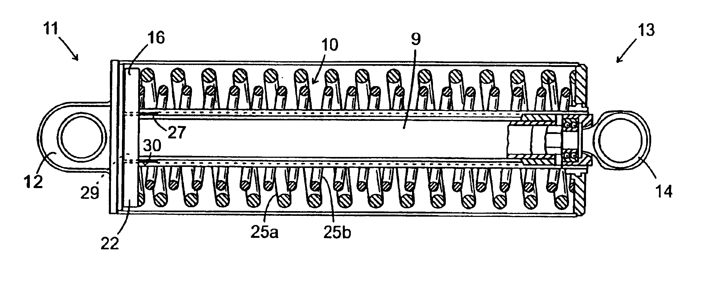
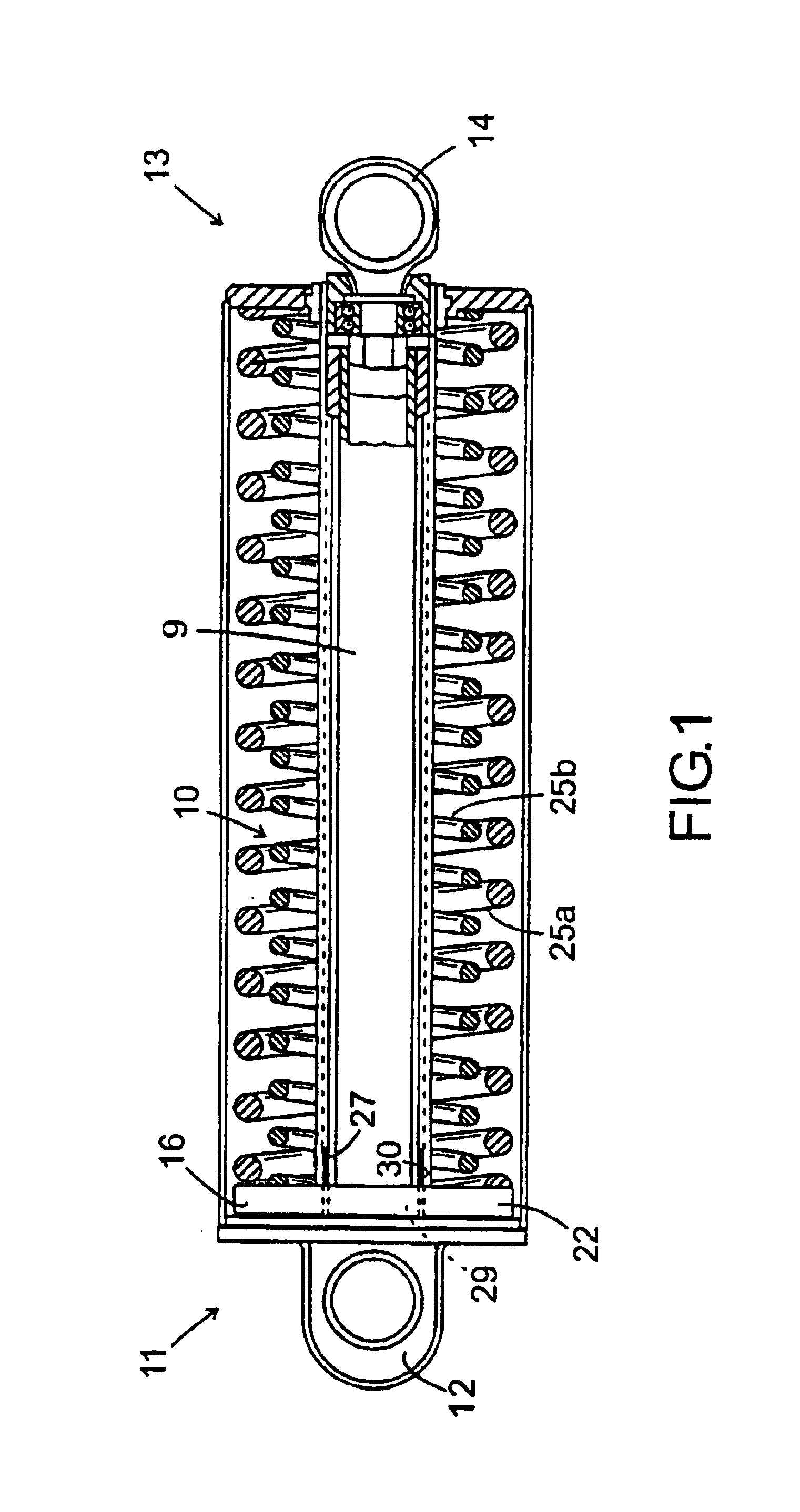
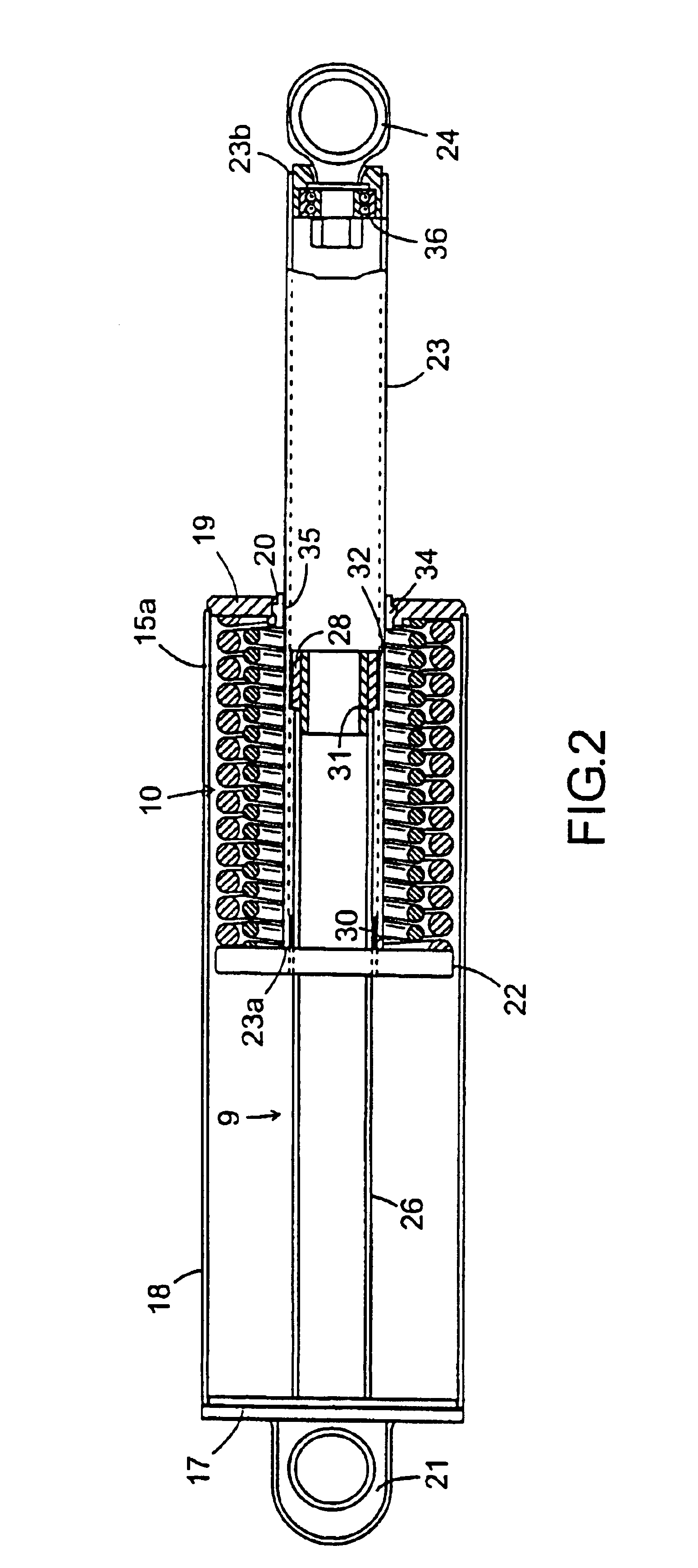
The aim of the invention is to, arrange a helical spring based balancing arrangement on a robot as above, where the robot manages to lift 250 kg with its wrist without damaging the balancing arrangement. The aim of the invention is also to provide the robot with a balancing arrangement, which has as long life expectance as the robot. Consequently, the object of the invention is to improve, in a balancing arrangement according to above, the guiding of a pull rod in a spring housing and by that eliminate the risk of obliquity of the pull rod, the so-called drawer effect.
It is within the scope of the invention that the spring housing is provided with aerating holes to eliminate pumping effects from the movement of the piston back and forth.

Problems solved by technology

Powerful power consuming motors are large, heavy and expensive, which commands a need of alternative solutions.
However, this leads to an increase in dead weight of both the motor and the balancing arrangement, which in turn calls for even bigger demands on the driving motor in question.
Apart from the counterweights the above mentioned devices are expensive, heavy and sensitive constructions.
Gashydraulic devices are space demanding and are furthermore marred by density problems.
In helical spring-based balancing cylinders there is always a risk for obliquity of the piston rod in relation to the cylinder, the so-called drawer effect, which when it arises leads to wear of the cylinder device and drastically shortened life-time.
The alternative with counterweights also results in disadvantages, because a robot with a counterweight can not be as compact and space-saving.
When the robot performs overly limited motion cycles, i.e. the robot is moving too little, problems with poor lubrication in the integral bearings arise.
When a helical spring is compressed there is always the risk that it deflects sideways i.e. bends / collapses.
With loads on the robot of up to 250 kg in the wrist a balancing arrangement is forced to work with very large torque forces and is easily damaged.
The damages usually originate through imbalance in the load of the balancing arrangement.
In the case with a helical spring, spring housing, spring seat and a pull rod an imbalance in the load of the pull rod, so-called drawer effect, leads to obliquity of the pull rod in the spring housing, wear appears and the expected life-time of the balancing arrangement is reduced to an unacceptably low level.
This leads to unwanted and expensive production interruptions.
Furthermore there will also be extra unwanted cost for spare equipment.
Load leads to large bending moments in the pull rod part in the spring housing, which results in very high strain in the construction, high surface pressures are generated and all this taken together results in the deflection of the pull rod.

Method used


Image

  • Industrial robot with a balancing device
  • Industrial robot with a balancing device
  • Industrial robot with a balancing device

Examples


Embodiment Construction

An industrial robot, comprising a manipulator with a control system, presents a robot foot, a stand and a robot arm with a wrist and a tool. The stand is pivotably arranged on the robot foot. The robot arm is pivotably arranged on the stand in a joint. The robot arm is composed of at least a first and a second arm part and also the wrist, all of which are pivotably arranged in relation to each other. A balancing arrangement is arranged to exert, when the robot is pivoted, a pulling force between a first and a second robot part and thereby to compensate for / balance the attraction of gravity when the relative position of the robot parts changes. The balancing arrangement is attached to the corresponding robot part with fastening devices.

The aim of the invention is to, arrange a helical spring based balancing arrangement on a robot as above, where the robot manages to lift 250 kg with its wrist without damaging the balancing arrangement. The aim of the invention is also to provide the ...


PUM


Abstract

Industrial robot arranged with a helical spring based balancing system, which is able to stand up to high load.

Description

TECHNICAL FIELDThe present invention relates to an industrial robot with an equalizing device, comprising a helical spring, and a method for balancing and use of the robot.BACKGROUNDIn industrial robots, comprising two robot parts pivotally arranged relative each other, powerful power consuming motors, which execute the pivoting of the robot, are required. Powerful power consuming motors are large, heavy and expensive, which commands a need of alternative solutions. One alternative is to supplement the robot with a device, which in the pivoting of the robot participates in the pivoting by absorbing the torque during the pivoting from a rest position / initial position, i.e. when the robot starts a work cycle. The concept pivoting from a rest position / initial position refers to a pivoting in a direction where the attraction of gravity contributes to the pivoting. The arrangement is of such a nature that it during the pivoting from the rest position generates a torque, which acts to res...

Claims


Application Information

Patent Timeline
IPC IPC(8): B25J19/00
CPCB25J19/0016Y10T74/20329Y10T74/20305
Inventor LUNDSTROM, CHRISTERNISSFOLK, RAFAEL
Owner ABB (SCHWEIZ) AG
Learn More