Multi-gimbal marine communication cable to ocean buoy transition interface

a technology of transition interface and communication cable, which is applied in the field of multi-gimbal configuration transition, can solve problems such as mechanical fatigue at the transition interface between the cable and the buoy

Inactive Publication Date: 2005-02-01
HARRIS CORP
View PDF7 Cites 67 Cited by
  • Summary
  • Abstract
  • Description
  • Claims
  • Application Information

AI Technical Summary

Benefits of technology

The outer surface of a generally cylindrically shaped wall of a relatively small diameter gimbal ring is tapered so as to form a pair of sloped wall regions. These sloped regions provide clearance so the rings can pivot and also keep the passageway open for the cable to pass. These sloped wall regions allow for pivotal movement of adjacent gimbal elements, and thereby the intended flexibility of the cable protecting structure which the multi-gimbal configured buoy-cable interface of the invention provides. An exterior surface of the first gimbal ring portion is provided with stop elements which limit the extent to which the second gimbal ring portion of an adjacent gimbal ring may pivot.

Problems solved by technology

Specifically, the substantially continuous (roll, pitch and yaw) motion of the buoy impart forces that act on the cable transition interface in three-dimensions and which, over time, introduce mechanical fatigue at cable and the transition interface.

Method used


Image

  • Multi-gimbal marine communication cable to ocean buoy transition interface
  • Multi-gimbal marine communication cable to ocean buoy transition interface
  • Multi-gimbal marine communication cable to ocean buoy transition interface

Examples


Embodiment Construction

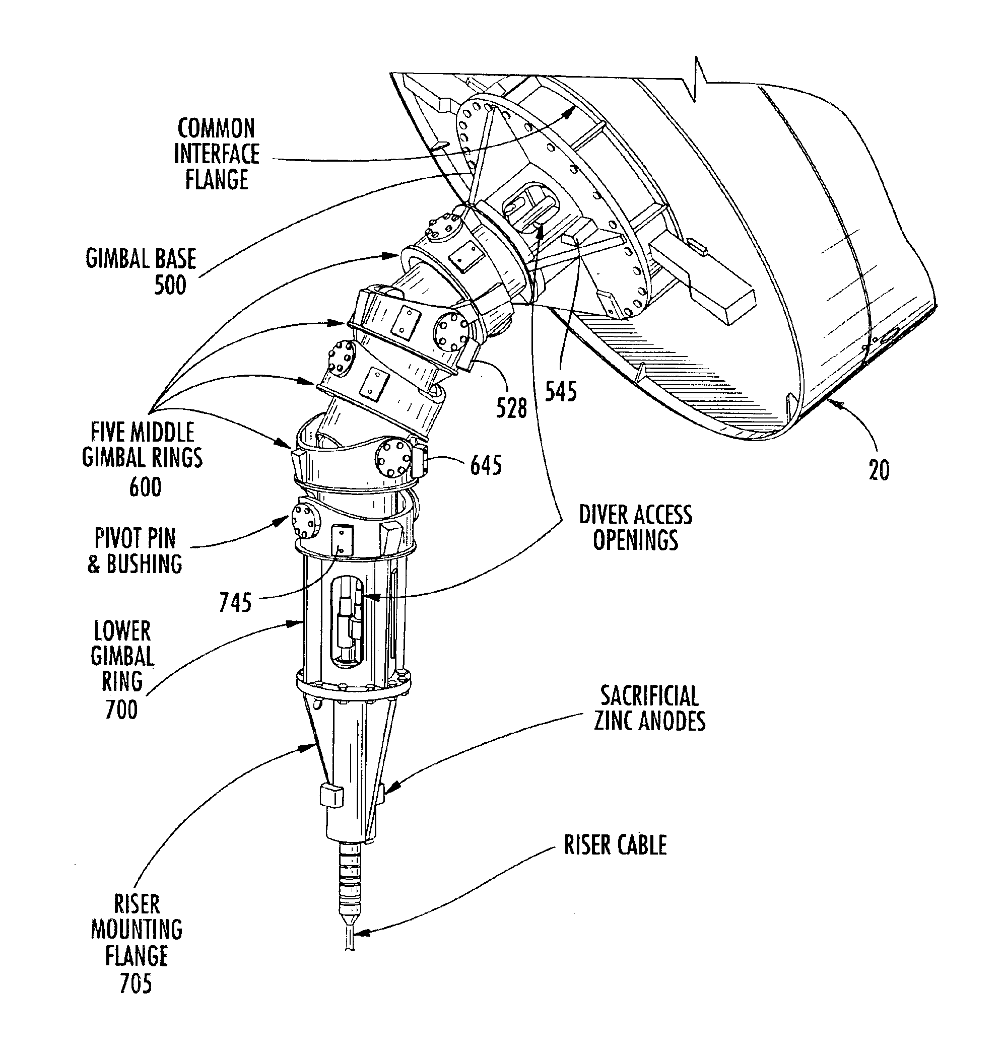
Attention is now directed to FIGS. 3 and 4, which show respective flexed and in-line assembled views of the multi-gimbal configured buoy-cable interface in accordance with the present invention, as well as FIGS. 5, 6 and 7, which illustrate in perspective a buoy attachment gimbal base, a middle gimbal ring, and a cable riser attachment lower gimbal ring, of which the multi-gimbal configured buoy-cable interface shown in FIGS. 3 and 4 is formed. All of the components are preferably made of a structurally rigid and rugged material such as steel. As shown in the assembled views of FIGS. 3 and 4, the multi-gimballed, flexible sheath structure of the invention comprises a cascaded interconnection of a single buoy attachment gimbal base 500, a plurality (five in the illustrated example) of middle gimbal rings 600, and a single cable riser attachment lower gimbal ring 700.

As described briefly above, attachment of the multi-gimbal configured sheath structure of the present invention to the ...


PUM


Abstract

A multi-gimbal configured transition protectively interfaces a mooring and communication cable to a communication ocean buoy. The transition interface contains a segmented, flexible sheath formed of a plurality of pivotally interconnected gimbal rings having mutually adjacent interior apertures through which one or more communication link members pass. Successive gimbal rings are orthogonally pivotally interconnected with one another so as to make the flexible sheath flexible in three dimensions. Upper ends of one or more communication link members are connectable with a communication cable connection fixture of the buoy. Lower ends of the communication link members are connectable to communication cable terminal connectors of a terminal end of the mooring cable.

Description

FIELD OF THE INVENTIONThe present invention relates in general to communication systems, subsystems and components therefor, and is particularly directed to a new and improved multi-gimbal configured transition for securely and protectively interfacing a mooring and communication cable to a communication ocean buoy.BACKGROUND OF THE INVENTIONOcean-deployed communication buoys, a reduced complexity depiction of one of which is shown in FIG. 1, are constantly being subjected to very dynamic forces that have made the integrity of the cable transition interface 10 between the keel 21 of the buoy 20 and a relatively static mooring / communication cable 30 an ongoing problem. Specifically, the substantially continuous (roll, pitch and yaw) motion of the buoy impart forces that act on the cable transition interface in three-dimensions and which, over time, introduce mechanical fatigue at cable and the transition interface. As a consequence, unless the transition interface between the cable a...

Claims


Application Information

Patent Timeline
Patent Type & Authority Patents(United States)
IPC IPC(8): B63B22/18B63B22/00F16L11/18F16L11/00H02G9/00H02G15/10H02G9/12H02G1/10H02G15/14
CPCB63B22/18H02G15/14H02G1/10H02G9/12F16L11/18B63B2203/00
Inventor SCHLIG, DANIEL LOUIS
Owner HARRIS CORP
Why Eureka
Try Eureka