Tensioner for a chain or belt

a technology of tensioner and chain, which is applied in the direction of belt/chain/gearing, mechanical equipment, belts, etc., can solve the problems of poor performance and even jamming, components require careful machining that is relatively expensive to perform, and not always ensure the appropriate tension is imparted to the chain

Inactive Publication Date: 2005-02-01
SCHAEFFLER KG
View PDF11 Cites 13 Cited by
  • Summary
  • Abstract
  • Description
  • Claims
  • Application Information

AI Technical Summary

Benefits of technology

The leading edge of the stop member is preferably rounded at its radially outer extremity so as to assist in its removal from the housing.
A locking member may be provided between the plunger and housing, the member being radially resilient and having an outside diameter greater than the inside diameter of the bore, the housing and plunger having respective locking grooves for receipt of the locking member, wherein the plunger is moveable from a locked position in which the locking member is trapped between the respective locking grooves so as to prevent extension of the plunger and an unlocked position in which the locking member is received in a relaxed state in the locking groove of the housing such that it does not project into the bore of the housing and the plunger is able to move relative to the housing and locking member.
According to a second aspect of the present invention there is provided a chain or belt comprising a plunger displaceable in a bore of a housing between retracted and extended positions and biased towards the extended position by a biasing member, the housing having a first recess and the plunger having a second recess, the first recess having a locking edge, and a radially resilient locking member that is slidable with the plunger relative to the housing from a first position in which it is trapped between said first and second recesses and abuts the locking edge so as to prevent movement of the plunger out of the housing and a second position in which it is received in the first recess such that it is clear of the plunger and allows it to move relative to the housing in either direction between extended and retracted positions.

Problems solved by technology

The incompressible nature of the hydraulic fluid prevents instant return movement of the plunger although a small annular clearance between the plunger and the cylinder wall may permit some fluid escape and limited slow retraction of the plunger.
The disadvantage of such ratchet mechanisms is that they are susceptible to poor performance and even jamming as a result of slight axial misalignment of the plunger in the chamber caused by the locking force is being applied on side only.
Moreover, the components require careful machining that is relatively expensive to perform.
Like the other aforementioned ratchet designs, the locking of the plunger against retraction at discrete positions does not always ensure the appropriate tension is imparted to the chain.

Method used


Image

  • Tensioner for a chain or belt
  • Tensioner for a chain or belt
  • Tensioner for a chain or belt

Examples


Embodiment Construction

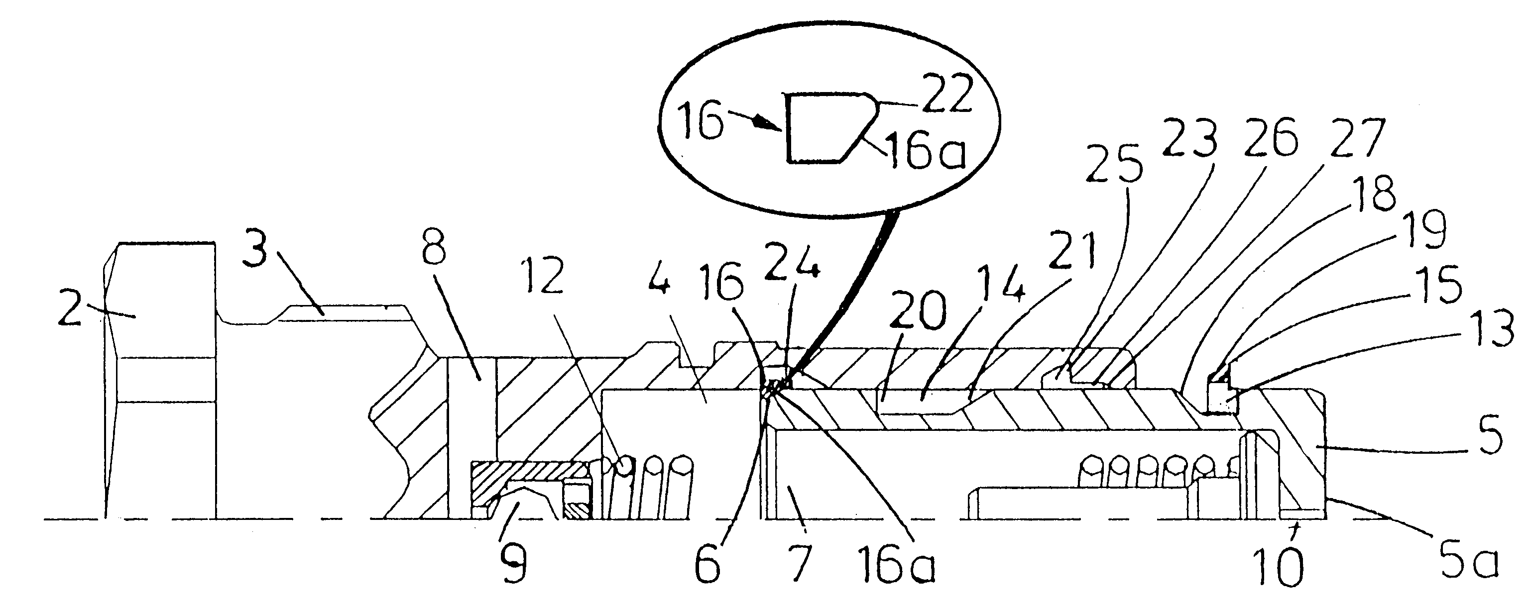
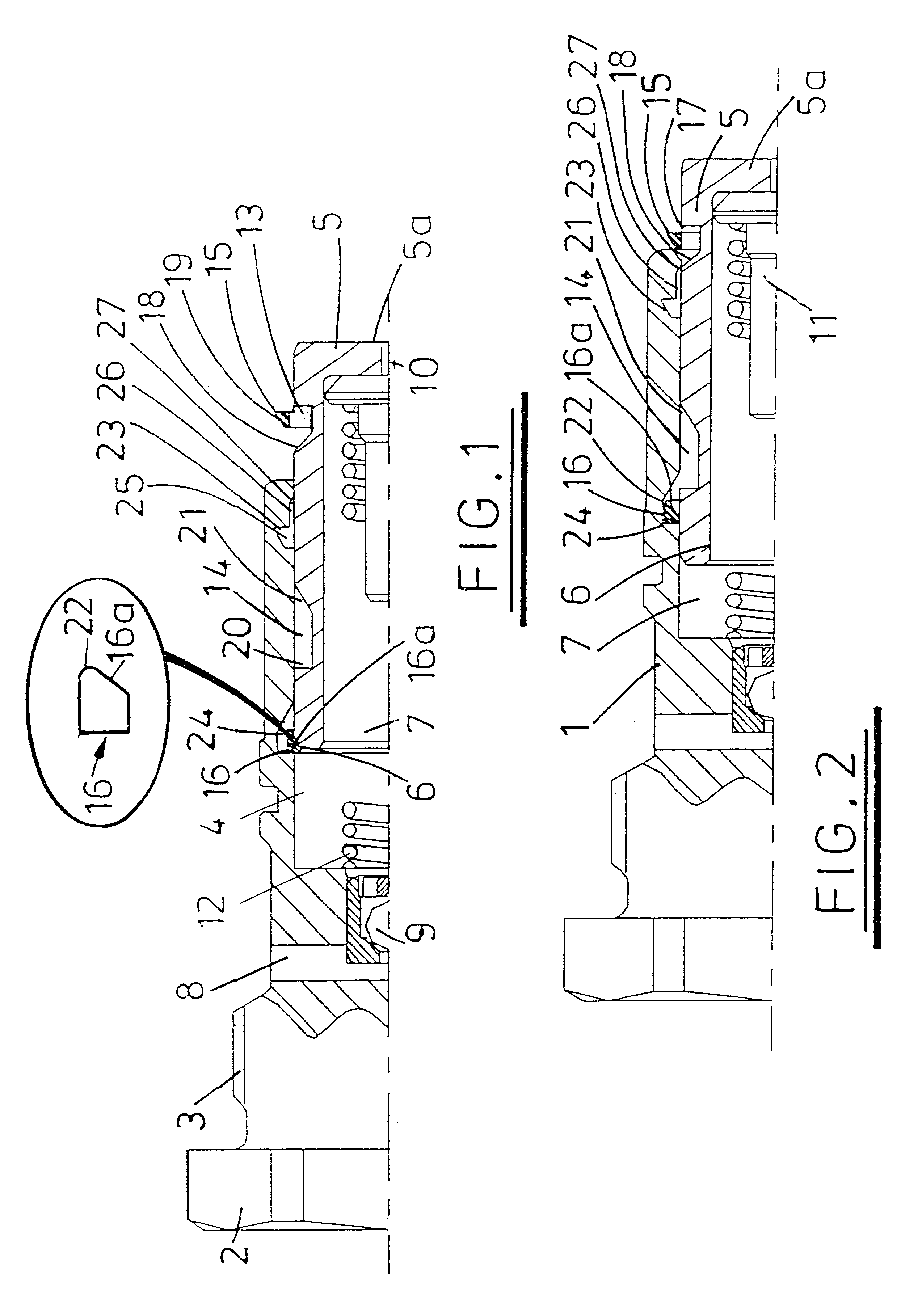
Referring now to the drawings, the exemplary chain tensioner has a body 1 that is designed to be inserted into a bore defined in an internal combustion engine cylinder block (not shown). To this end the body 1 has, at one end, a head 2 with a plurality of flats for engagement with an appropriate fastening tool and an adjacent threaded portion 3 by which the tensioner is screw-engaged in the engine bore.

The tensioner body 1 is generally cylindrical and has a blind bore 4 that is open at one end to receive a slidable hollow plunger 5. The exposed end 5a of the plunger 5 is closed and engageable with a movable chain guide or shoe (not shown). The other end of the plunger 5 has a chamfered outer edge 6 the purpose of which will become apparent later.

The interior of the bore 4 and the plunger 5 define a variable volume pressure chamber 7 that is filled with hydraulic oil. The chamber 7 is supplied with oil from an oil reservoir (not shown) via a passage 8 and a ball check valve 9. When t...


PUM


Abstract

A chain or belt tensioner comprises a plunger displaceable in a housing between retracted and extended positions. A stop ring between the plunger and housing frictionally contacts a smooth surface of the housing. A recess in the plunger has a tapered face for engagement with a bevelled surface of the stop ring. Inward movement of the plunger causes the tapered face to engage the stop ring and to force it to deform outwardly to a wedging position in which the stop ring is wedged between the tapered face and the surface thus preventing further inward movement of the plunger. The recess has a second face that engages the stop ring when the plunger moves out of the housing so as to slide it over the surface. The invention provides for a stop mechanism that enables retraction of the plunger to be prevented at an infinite number of positions.

Description

CROSS-REFERENCE TO RELATED APPLICATIONSThis application claims priority under 35 U.S.C. § 119 to Great Britain Patent Application No. 0025246.0 filed Oct. 13, 2000.STATEMENTS REGARDING FEDERALLY SPONSORED RESEARCH OR DEVELOPMENTNot Applicable.REFERENCE TO A MICROFICHE APPENDIXNot Applicable.BACKGROUND1. Field of InventionThe present invention relates to a tensioner for a chain or belt and more particularly, but not exclusively, to a tensioner for imparting tension to a chain or belt used in a timing drive of an internal combustion engine of a vehicle.2. Description of Related ArtInternal combustion engines of motor vehicles often include a timing belt or chain drive that passes over sprockets on the crankshaft and camshaft and is used to ensure that the camshaft is driven synchronously with the crankshaft. The tension in such a chain or belt varies considerably as a result of the expansion and contraction of engine components with temperature, torsional vibrations imparted from the ...

Claims


Application Information

Patent Timeline
Patent Type & Authority Patents(United States)
IPC IPC(8): F16H7/08
CPCF16H7/0848F16H2007/0806F16H2007/0859F16H2007/0851F16H2007/0812
Inventor POIRET, CHRISTIANCHARTON, ALEXANDRE
Owner SCHAEFFLER KG
Why Eureka
Try Eureka