
Barber pole structure for magnetoresistive sensors and method of forming same

a barbed pole and magnetoresistive technology, applied in the field of magnetoresistive sensors, can solve the problems of bridge output, laser trimming adds cost to devices, and upsets the balan

Inactive Publication Date: 2005-02-01
HONEYWELL INT INC
View PDF4 Cites 20 Cited by
  • Summary
  • Abstract
  • Description
  • Claims
  • Application Information

AI Technical Summary

Problems solved by technology

The use of barber poles, however, can upset this balance, such as where the barber poles are not uniformly formed over the magnetoresistive material of the four sensors.
As described above, an imbalance causes the bridge to have an output even when no magnetic field is present.
However, laser trimming adds cost to devices such as Wheatstone bridges which use magnetoresistive sensors.

Method used


Image

  • Barber pole structure for magnetoresistive sensors and method of forming same
  • Barber pole structure for magnetoresistive sensors and method of forming same
  • Barber pole structure for magnetoresistive sensors and method of forming same

Examples


Embodiment Construction

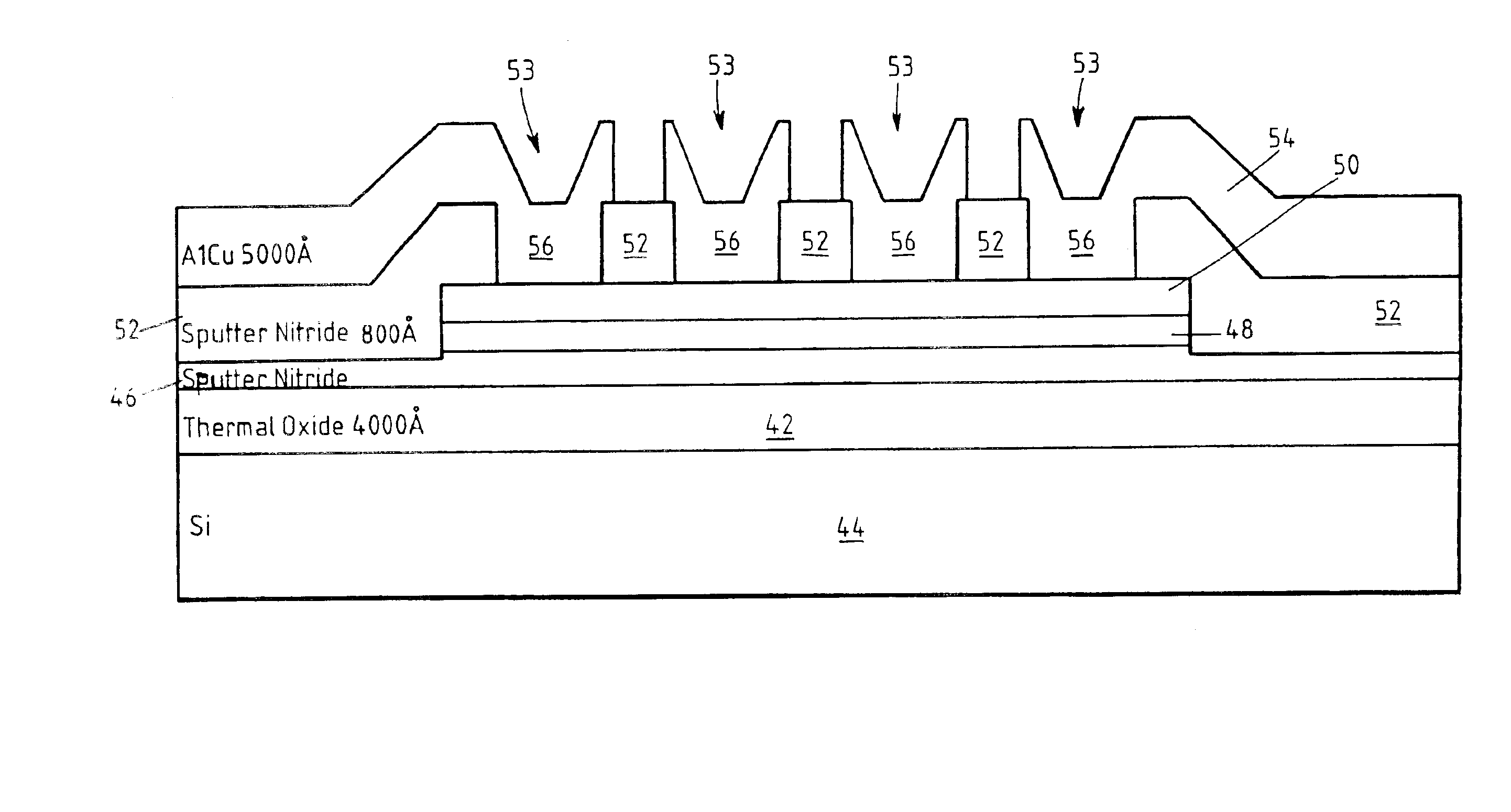
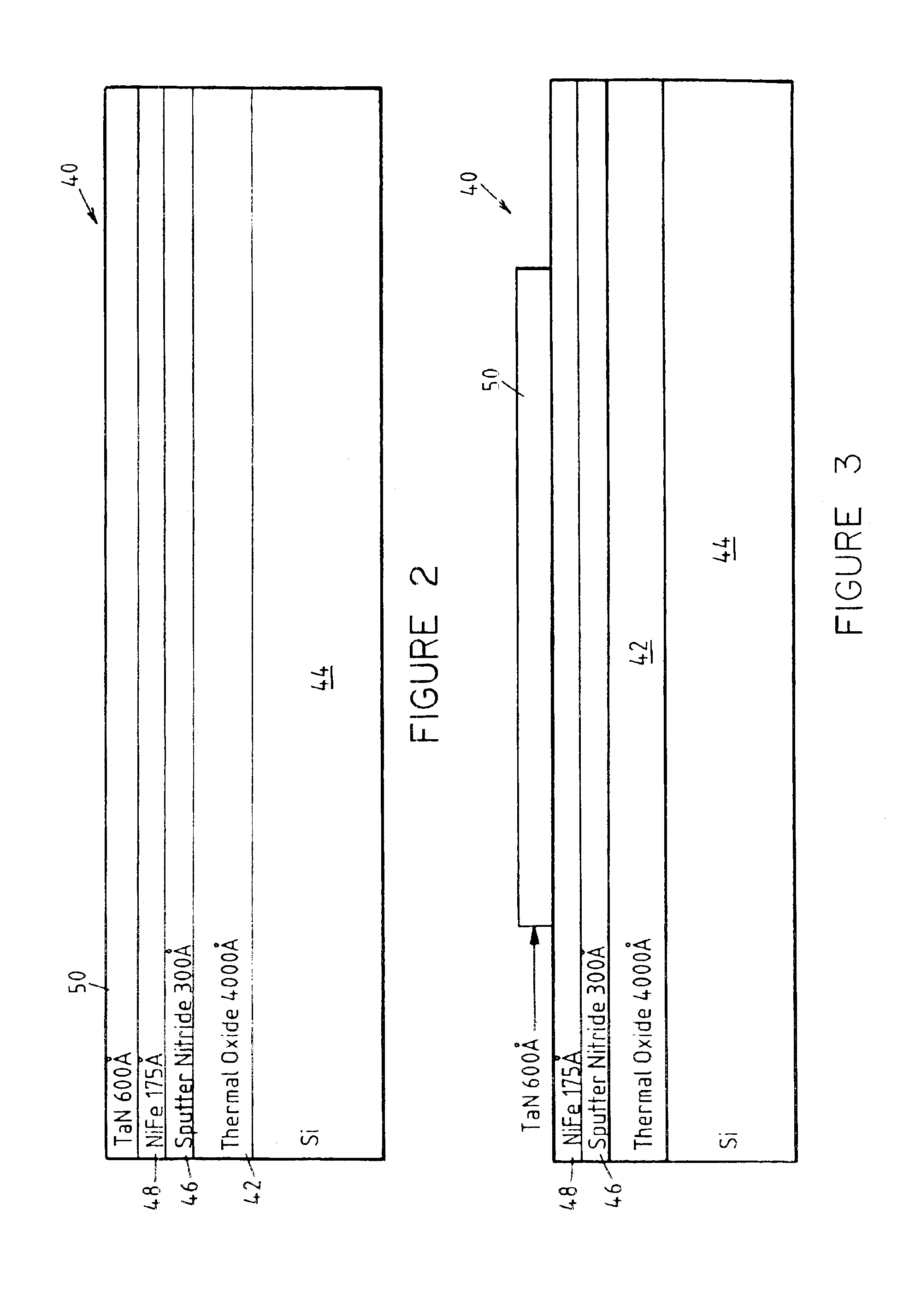
A magnetoresistive sensor 40 as illustrated in FIG. 2 is produced by depositing a thermal oxide layer 42 over a silicon substrate 44. (The view in FIG. 2 is a side view of one magnetoresistive sensor.) The thermal oxide layer 42 is a dielectric layer used to electrically isolate the silicon substrate 44 from the rest of the magnetoresistive sensor 40 and may have a thickness of, for example, 4000 Å. A nitride layer 46 is sputtered over the thermal oxide layer 42. The nitride layer 46 may have a thickness of, for example, 300 Å. Over the nitride layer 46 is deposited a Permalloy layer 48 to a thickness, for example, of 175 Å, and a tantalum nitride layer 50 is deposited over the Permalloy layer 48 to a thickness, for example, of 600 Å.

The nitride layer 46 provides an atomically smooth surface for the Permalloy layer 48, and creates a barrier between the thermal oxide layer 42 and the Permalloy layer 48. The tantalum nitride layer 50 provides a good hard etch mask and a good barrier t...


PUM

PropertyMeasurementUnit
Diffusion barrieraaaaaaaaaa
Dielectric polarization enthalpyaaaaaaaaaa
Electrical resistanceaaaaaaaaaa

Abstract

A method of making a magnetorestrictive sensor involves the deposition of a magnetorestrictive strip over a substrate, the deposition of an insulating layer over the magnetorestrictive strip, the etching of barber pole windows through the insulating layer, the deposition of a conductive material over the insulating layer and into the barber windows, and the etching away of the conductive material between the barber pole windows so as to form barber poles. In this manner, the formation of the barber poles is controlled by the windows formed in the insulating layer.

Description

TECHNICAL FIELD OF THE INVENTIONThe present invention relates in general to magnetic field sensors and, more particularly, to magnetoresistive sensors.BACKGROUND OF THE INVENTIONMagnetoresistive sensors are typically small and can generally measure magnetic fields on the order of 0.001 gauss to 100 gauss. Also, magnetoresistive sensors are able to measure D.C. fields as well as fields having frequencies up to and exceeding a megahertz. Accordingly, magnetoresistive sensors are used in a wide variety of applications such as current sensing, proximity sensing, etc.The magnetoresistive material used in making magnetoresistive sensors is a material whose resistance changes in the presence of a magnetic field. Permalloy, which is a nickle / iron alloy, is such a material and is often provided as a film for use in magnetoresistive sensors. The resistance of the film varies according to the square of the cosine of the angle between the magnetization direction and the current direction.The re...

Claims


Application Information

Patent Timeline
IPC IPC(8): G01R33/06G01R33/09H01L41/12H01L41/20H01L41/22H01L41/47
CPCG01R33/09G01R33/096Y10T428/1186Y10T428/12958
Inventor WITCRAFT, WILLIAM F.BERG, LONNYNG, MAE W.YEH, TOM
Owner HONEYWELL INT INC
Learn More