System for introducing optical tweezers and/or a treatment beam into a laser scanning microscope

a laser scanning microscope and treatment beam technology, applied in the field of systems, can solve the problems of limited conventional microscope application, inability to achieve satisfactory images, and inability to access the specimen from abov

Inactive Publication Date: 2005-02-01
CARL ZEISS MICROSCOPY GMBH
View PDF15 Cites 35 Cited by
  • Summary
  • Abstract
  • Description
  • Claims
  • Application Information

AI Technical Summary

Problems solved by technology

LSM recordings of moving objects, above all in the interior of unopened cells, often do not result in satisfactory images because many subcellular structures move during the scanning time.
However, this is undesirable during image recording.
Further, this type of in-coupling limits conventional microscope applications because the objective for the optical tweezers is placed at the location of the transmitted light beam path in the inverted microscope.
Moreover, there is no longer unlimited free access to the specimen from above, which makes applications with microinjection devices or temperature regulating devices, for example, very difficult, if not impossible.
In addition, problems arise with respect to the sterility of the specimen because the glass fibers must be immersed in thicker liquid layers when particles are to be fixated on the underside of the liquid.

Method used


Image

  • System for introducing optical tweezers and/or a treatment beam into a laser scanning microscope
  • System for introducing optical tweezers and/or a treatment beam into a laser scanning microscope
  • System for introducing optical tweezers and/or a treatment beam into a laser scanning microscope

Examples


Embodiment Construction

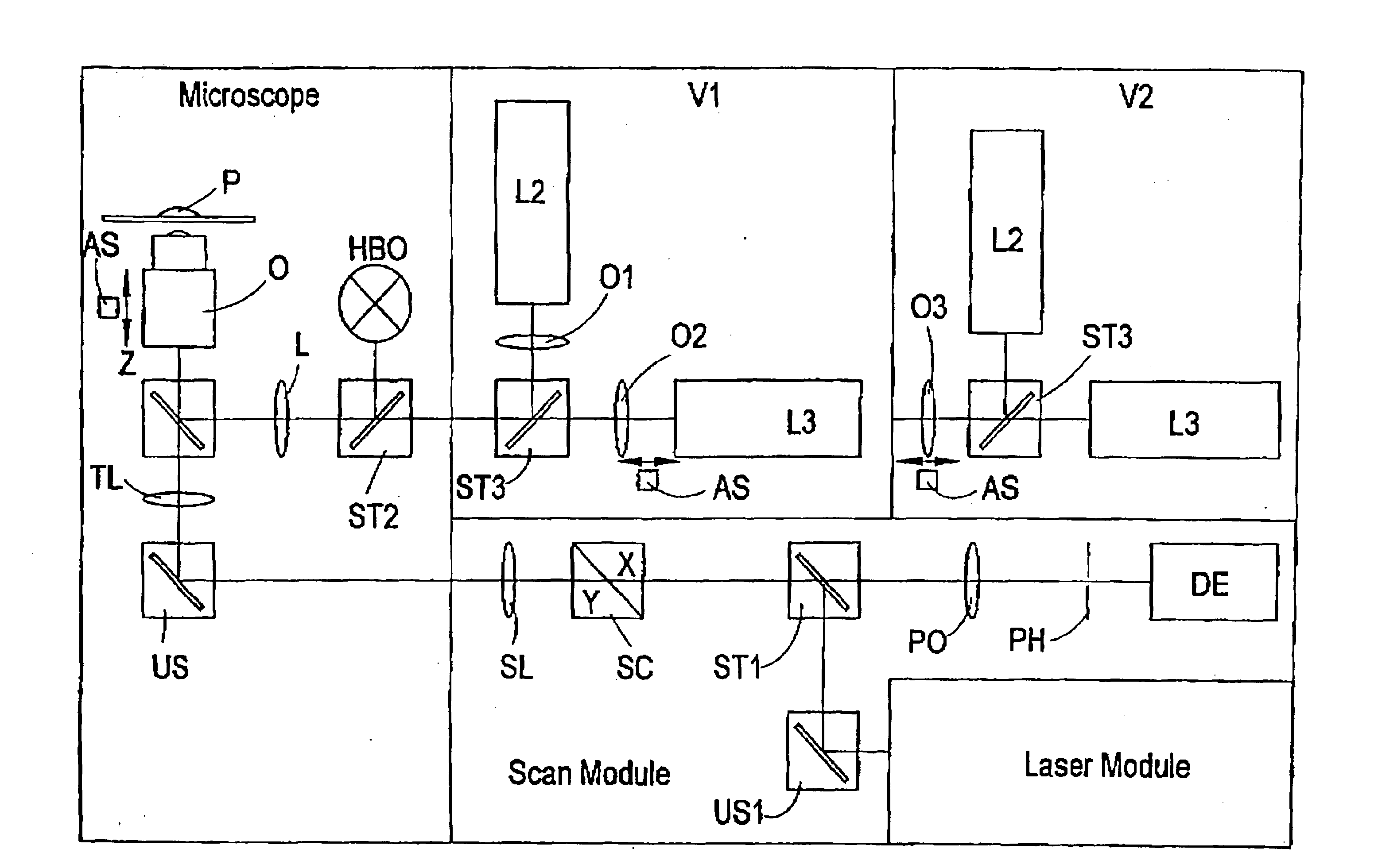
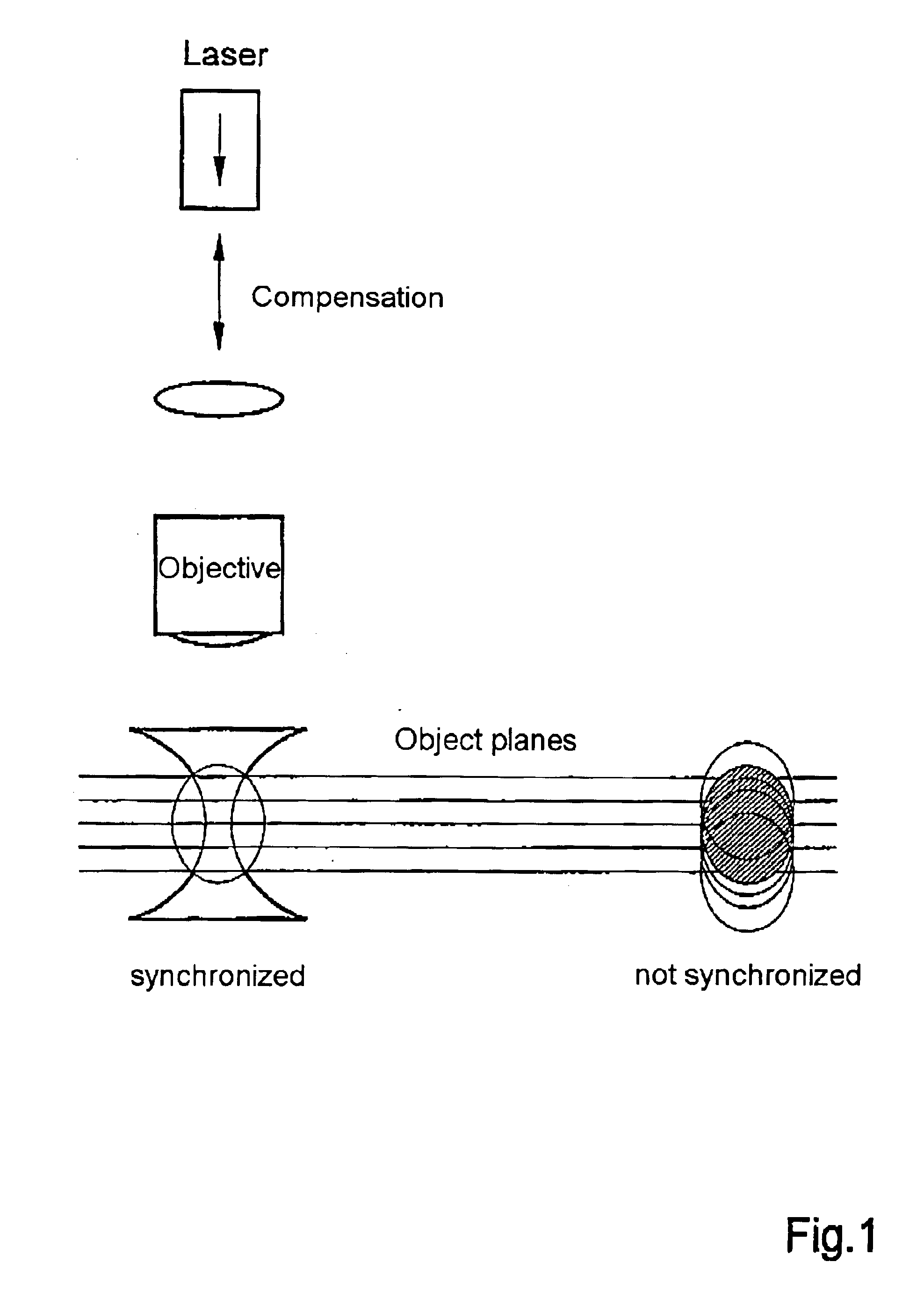
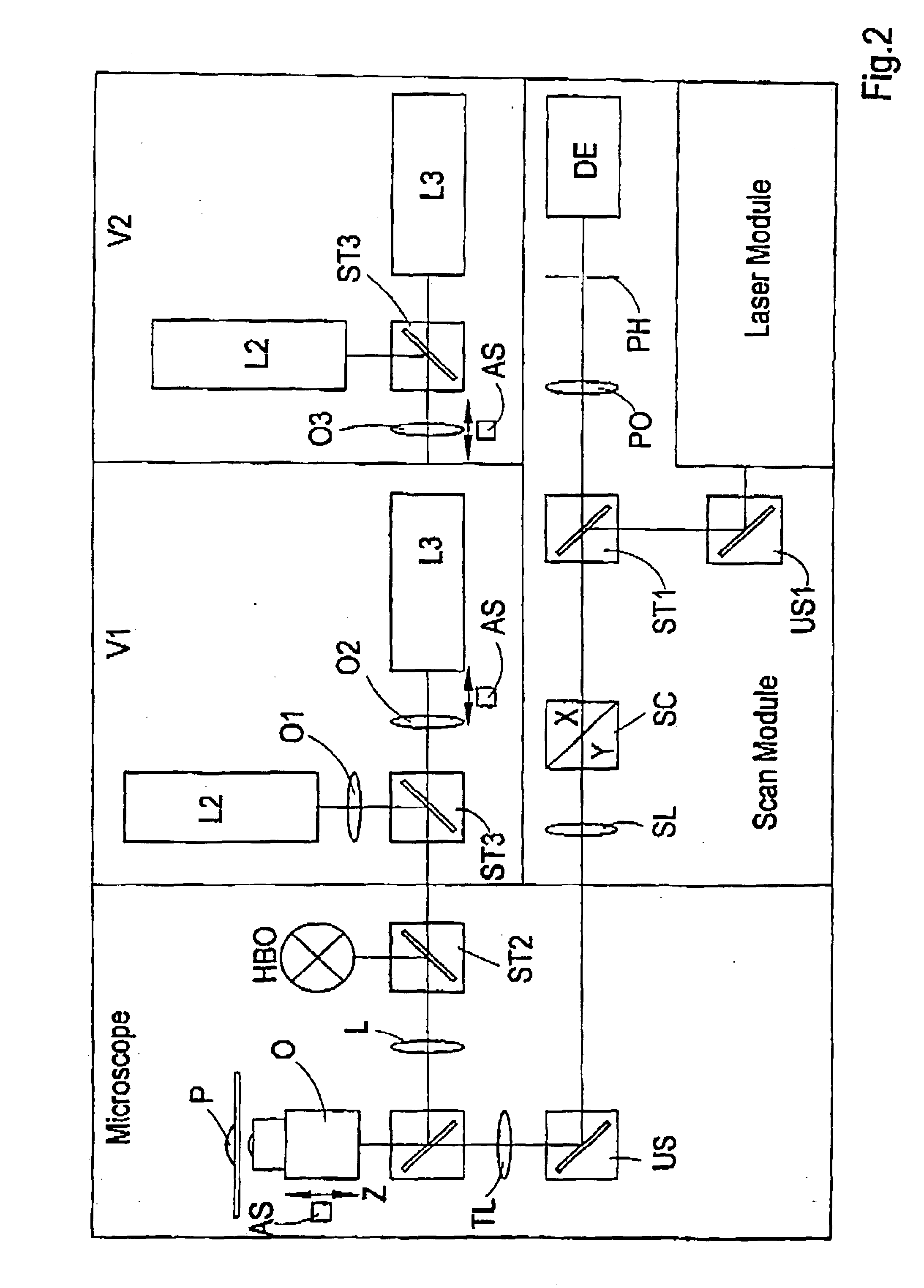
In the construction which is relevant for the invention, the optical tweezers are guided through the microscope objective into the object plane. They are adjusted in such a way that microscopic particles located in the object plane are fixed, that is, the focus of the optical tweezers lies in the object plane. However, in three-dimensional image recording through a laser scanning microscope, the object plane must be displaced in parallel in order to access the third dimension projecting out of the object plane. Accordingly, the focus of the optical tweezers is also displaced, which leads to an unwanted displacement of the fixated particles. Three-dimensional objects that are held by the optical tweezers can not be recorded in three-dimensional resolution without compensating for this displacement. Compensation of the displacement of the object plane, hereinafter referred to as z-compensation, comprises variable optical elements which are inserted into the beam path of the optical tw...


PUM


Abstract

An arrangement for coupling at least one beam of optical tweezers for trapping particles and / or a treatment beam into a microscope beam path, preferably in a laser scanning microscope, wherein means are provided for changing the position of the beam focus of the optical tweezers and / or of the treatment beam in a freely adjustable manner for purposes of changing the focal position of the microscope.

Description

BACKGROUND OF THE INVENTIONa) Field of the InventionThe invention enables spatial fixation of microscopic objects in laser scanning microscopes, also during the displacement of the object plane, for example, when recording an image. Therefore, moving objects can also be imaged sharply.b) Related BackgroundOptical tweezers have proven to be an important work tool for a range of biological work techniques. Expanded experimental possibilities can be anticipated due to the combination of laser scanning microscopes with laser micro-techniques.LSM recordings of moving objects, above all in the interior of unopened cells, often do not result in satisfactory images because many subcellular structures move during the scanning time. Ideally, the optical tweezers can be used for careful (vital) fixation. Further, a spatially defined displacement of fixed objects is possible with the optical tweezers. Application examples for the use of compensated optical tweezers in the laser scanning microsc...

Claims


Application Information

Patent Timeline
Patent Type & Authority Patents(United States)
IPC IPC(8): G02B21/00G21K1/00G02B7/04G02B21/24G02B21/32
CPCG02B21/002
Inventor WENDENBURG, RONALDMICHELMANN, ANJAGREULICH, KARL OTTOMONAJEMBASHI, SHAMCIUHL, VOLKER
Owner CARL ZEISS MICROSCOPY GMBH
Why Eureka
Try Eureka