Arrangement for illumination and/or detection in a microscope
- Summary
- Abstract
- Description
- Claims
- Application Information
AI Technical Summary
Benefits of technology
Problems solved by technology
Method used
Image
Examples
Embodiment Construction
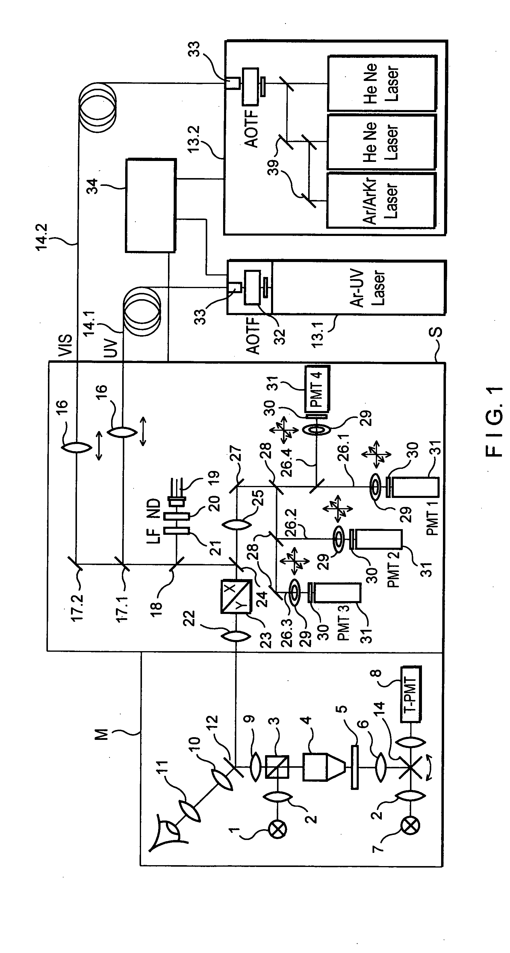
[0033]FIG. 1 shows schematically a microscope unit M and a scan head S which have a common optical interface via an intermediate image and form an LSM.
[0034] The scan head S can be mounted on the phototube of an upright microscope as well as on a lateral output of an inverse microscope.
[0035] The drawings show a microscope beam path which is switchable between incident light scanning and transmitted light scanning by means of a swivelable mirror 14, with a light source 1, illumination optics 2, beam splitter 3, objective 4, specimen stage 5, condenser 6, light source 7, receiver arrangement 8, a tube lens 9, an observation beam path with a tube lens 10 and an eyepiece 11, and a beam splitter / mirror 12 for coupling in the scanning beam. A laser module 13.1, 13.2 holds the laser and is connected via monomode light-conducting fibers 14.1, 14.2 with the laser input coupling unit of the scan head S.
[0036] The coupling of radiation into the light-conducting fibers 14.1, 14.2 is carried...
PUM
 Abstract
Description
Claims
Application Information
 - R&D
- Intellectual Property
- Life Sciences
- Materials
- Tech Scout
- Unparalleled Data Quality
- Higher Quality Content
- 60% Fewer Hallucinations
Browse by: Latest US Patents, China's latest patents, Technical Efficacy Thesaurus, Application Domain, Technology Topic, Popular Technical Reports.
© 2025 PatSnap. All rights reserved.Legal|Privacy policy|Modern Slavery Act Transparency Statement|Sitemap|About US| Contact US: help@patsnap.com


