Calibration device and laser scanning microscope with such a calibration device

a laser scanning microscope and calibration device technology, applied in the direction of optical radiation measurement, fluorescence/phosphorescence, luminescent dosimeters, etc., can solve the problem of managing the variety of performance tests and/or calibration tasks

Active Publication Date: 2009-09-10
CARL ZEISS MICROSCOPY GMBH
View PDF4 Cites 22 Cited by
  • Summary
  • Abstract
  • Description
  • Claims
  • Application Information

AI Technical Summary

Benefits of technology

[0016]The test structure can advantageously have reflecting grating elements as structural elements. Such structural elements, consisting of chromium, for example, proved to be particularly suitable, since they permit calibration of the scanning field sizes, linearity of the scanner movement or correction of nonlinearities in the imaging properties of the optical system. In particular, the grating elements can be designed as gratings periodically structured in the x- and y-direction, which can also have different period lengths to implement different scanning frequencies.
[0017]For adjustment and calibration of modem microscopes that detect fluorescence light, calibration devices are required that can emit fluorescence light as a response to irradiation with excitation light. It is therefore advantageous where fluorescent intermediate grating areas are formed between the reflecting grating elements.

Problems solved by technology

Consequently, there is the problematic task of managing the variety of performance tests and / or calibration tasks with simple means in time-saving fashion.

Method used


Image

  • Calibration device and laser scanning microscope with such a calibration device
  • Calibration device and laser scanning microscope with such a calibration device
  • Calibration device and laser scanning microscope with such a calibration device

Examples


Embodiment Construction

[0040]In describing preferred embodiments of the present invention illustrated in the drawings, specific terminology is employed for the sake of clarity. However, the invention is not intended to be limited to the specific terminology so selected, and it is to be understood that each specific element includes all technical equivalents that operate in a similar manner to accomplish a similar purpose.

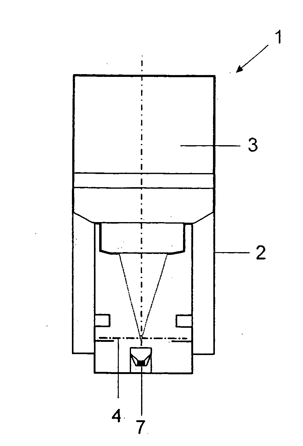
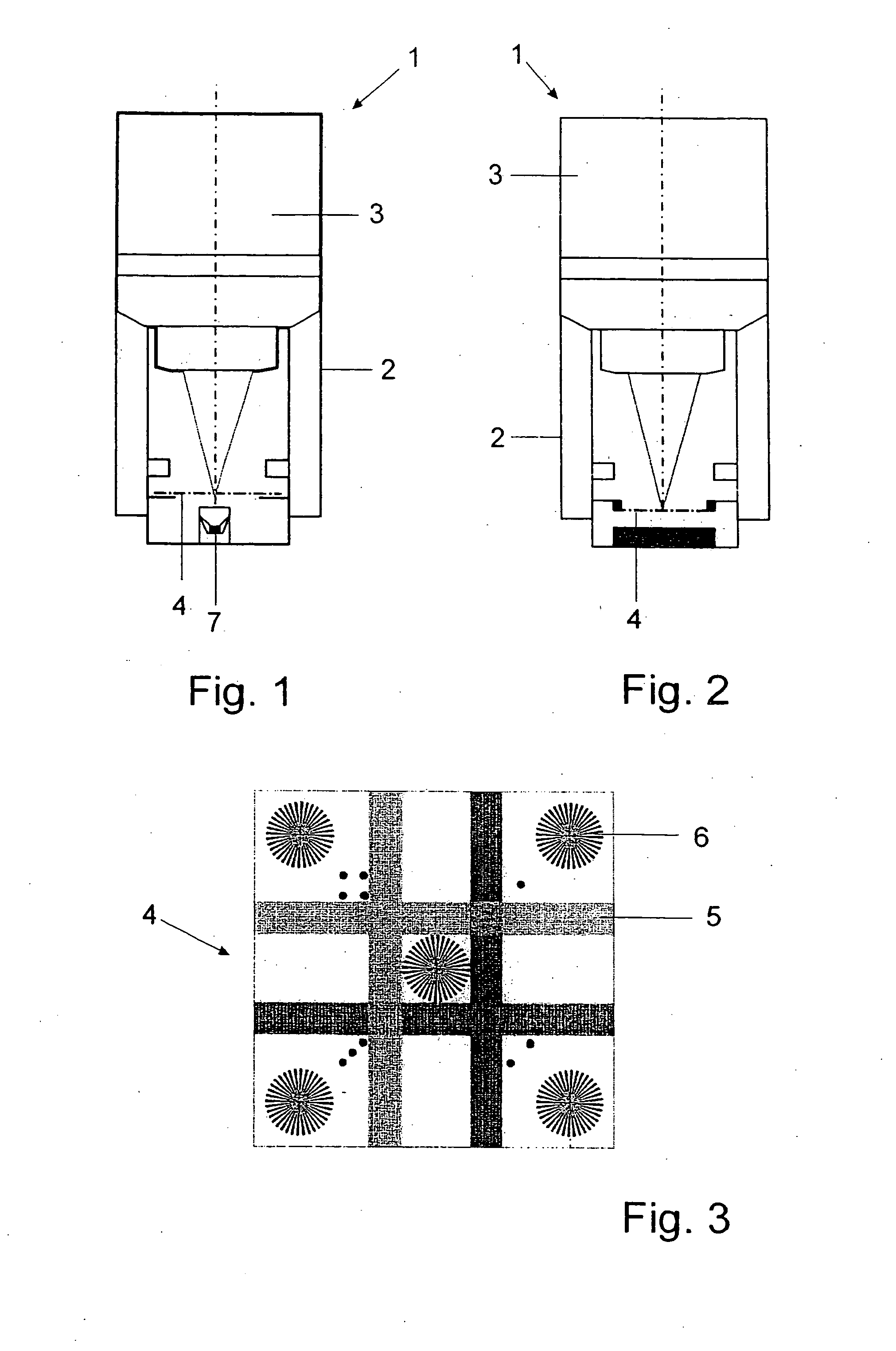
[0041]The calibration device 1 depicted in FIG. 1 contains focusing optics 3 and a test structure 4, arranged replaceable in the focal plane FE of focusing optics 3 and adjusted to focusing optics 3 in a common mounting 2. The fixed positioning of focusing optics 3 and test structure 4 relative to each other guarantees the ability to conduct control measurements over time. The test structure 4 has geometric structural elements and / or elements defined by material properties that are detectable in reflected light and / or transmitted light.

[0042]In the embodiment according to FIG. 3, the stru...


PUM

PropertyMeasurementUnit
thicknessesaaaaaaaaaa
grating periodaaaaaaaaaa

Abstract

A calibration device for managing a variety of performance tests and/or calibration tasks in a laser scanning microscope. The calibration device, which has focusing optics and a test structure arranged in the focal plane of the focusing optics, with structural elements detectable in reflected and/or transmitted light aligned to each other in a common mounting, can be switched into the microscope beam path in a laser scanning microscope, so that the pupil of the focusing optics coincides with the objective pupil of the laser scanning microscope or lies in a plane conjugated to it.

Description

CROSS-REFERENCE TO RELATED APPLICATIONS[0001](Not Applicable)STATEMENT REGARDING FEDERALLY SPONSORED RESEARCH OR DEVELOPMENT[0002](Not Applicable)REFERENCE TO A “SEQUENCE LISTING,” A TABLE, OR A COMPUTER PROGRAM LISTING APPENDIX[0003](Not Applicable)BACKGROUND OF THE INVENTION[0004](1) Field of the Invention[0005](2) Description of Related Art including information disclosed under 37 CFR 1.97 and 1.98[0006]Laser radiation generated by at least one laser as an excitation beam is guided in confocal laser scanning microscopes (LSM) via a scanner, scanning optics and a tube lens and is focused in a sample under investigation by means of an objective with limited diffraction. Because of interaction of the excitation beam with the sample or preparation, emitted fluorescence radiation goes via the scanner to a dichoroic beam splitter, which directs the fluorescence radiation into a detection beam path separately from the excitation radiation. The fluorescence radiation is then focused on a...

Claims


Application Information

Patent Timeline
Patent Type & Authority Applications(United States)
IPC IPC(8): G01N21/64G02B21/06
CPCG01M11/0264G02B27/32G02B21/34G02B21/002
Inventor NETZ, RALFBATHE, WOLFGANGSTEINERT, JOERGKLEINSCHMIDT, WERNERFAHLBUSCH, INGOBREHM, MICHAEL
Owner CARL ZEISS MICROSCOPY GMBH
Why Eureka
Try Eureka