
Optical resonators with orthogonally polarized modes

a technology of optical resonators and orthogonal polarization, which is applied in the direction of optical resonator shape and construction, electrical equipment, laser details, etc., can solve the problem that the gain of any region utilized by one of the beams is no longer available for utilization by the other beam, and achieve the effect of increasing the utilization of gain medium, and increasing the utilization of laser gain volum

Inactive Publication Date: 2005-02-01
YEDA RES & DEV CO LTD
View PDF23 Cites 18 Cited by
  • Summary
  • Abstract
  • Description
  • Claims
  • Application Information

AI Technical Summary

Benefits of technology

The present invention provides an optical resonator with higher efficiency and brighter output than previous designs. The resonator has reflector elements at its ends, with a polarizing element and mode-controlling elements in between. The mode-controlling elements can be separate elements or positioned in the reflector elements or output couplers. The resonator has two stable modes, and the gain medium is designed to allow the modes to interact without interference. The resonator can be an active or passive resonator, and each path can have a single mode control element or a set of modes. The output beam has two orthogonal polarizations, and a phase element can be used to focus the beam to a small focal spot. The invention also provides an improved optical resonator with a single mode control element that allows for the co-existence of two modes without interference.

Problems solved by technology

Also, the resonator may be a stable or unstable resonator.
Specifically, the gain of any region utilized by one of the beams is no longer available for utilization by the other beam.

Method used


Image

  • Optical resonators with orthogonally polarized modes
  • Optical resonators with orthogonally polarized modes
  • Optical resonators with orthogonally polarized modes

Examples


Embodiment Construction

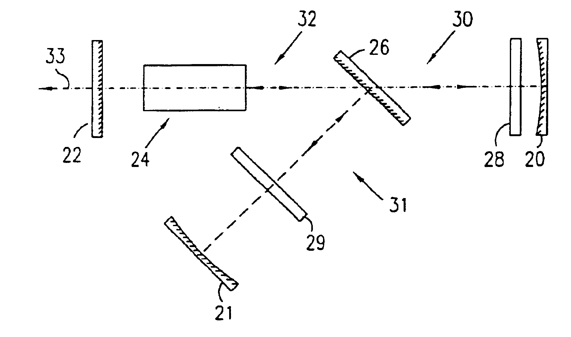
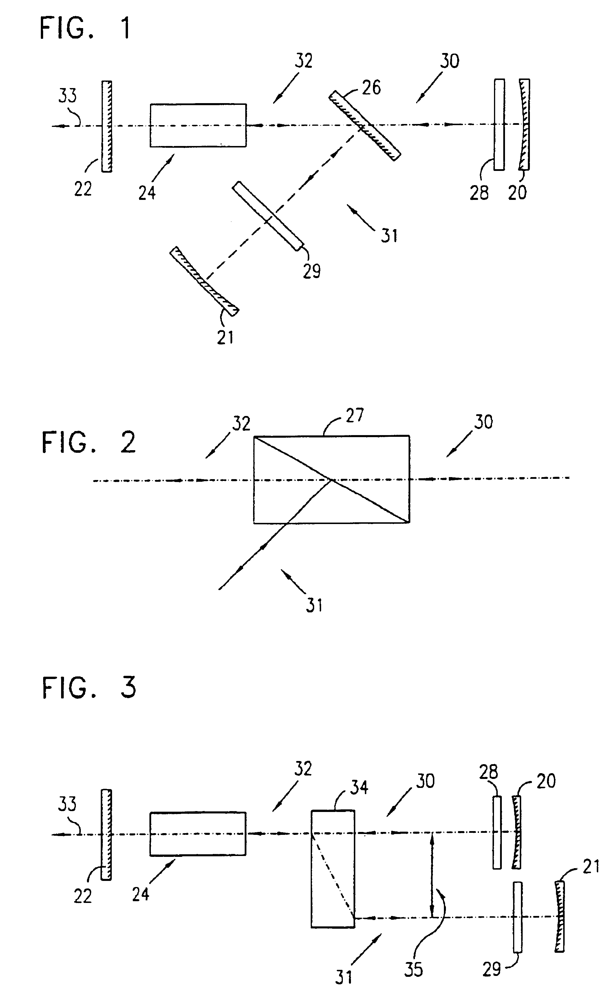
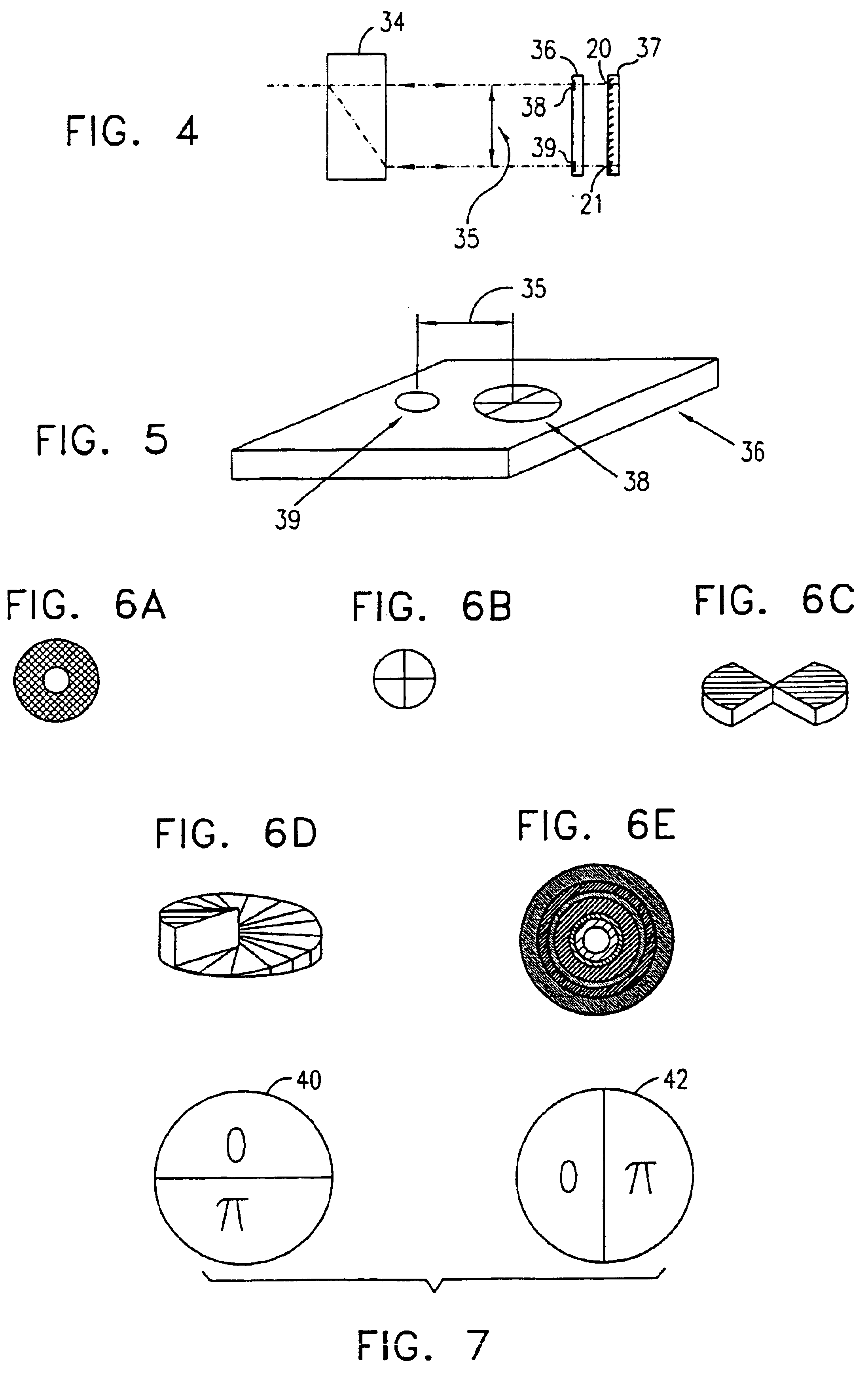
Reference is now made to FIG. 1, which is schematic illustration of a linear resonator of a laser constructed and operative in accordance with a preferred embodiment of the present invention. The linear resonator preferably consists of reflectors, preferably full reflectors 20 and 21 and a partial reflector or an output coupler 22, a gain medium 24, a thin film polarizing beam splitter 26 and two mode controlling elements 28 and 29. The beam splitter 26 reflects one polarization, hereinafter called polarization “1”, through control element 29 towards full reflector 21, and transmits the polarization orthogonal to polarization “1”, hereafter called polarization “2”. Two modes of oscillation, indicated by reference numbers 30 and 31 are thus established between the output coupler 22 and the reflectors 20 and 21 respectively. Both radiation associated with both modes 30 and 31 propagate through the gain medium 24. However, the radiation associated with mode 30 propagates through the mo...


PUM


Abstract

An optical resonator supporting two sets of simultaneously co-existent oscillation modes (30 and 31), having polarizations orthogonal to each other. Mode control elements (28 and 29), such as apertures and phase elements, are introduced into the resonator to allow only preferred modes to exist. The placement and orientation of the sets are designed such that the high intensity zones of one set fall on the nodes or low intensity zones of the other set in an interlaced pattern. Thus, in a laser resonator, better utilization of the gain medium (24) is achieved and the beam quality and brightness over multimode lasing are improved. This configuration improves the performance of high Fresnel number resonators, in both pulsed and continuous lasers, for applications such as scribing, drilling, cutting, target designation and rangefinding. An application of the intra-cavity coherent summation of orthogonally polarized modes is described, whereby azimuthally or radially polarized beams may be obtained.

Description

FIELD OF THE INVENTIONThe present invention relates in general to the field of optical resonators and in particular to those used in lasers.BACKGROUND OF THE INVENTIONIn general, the intensity distribution of light emerging from optical resonators, especially those used in high power lasers with large apertures, has a multimode pattern. In this pattern, the intensity is typically distributed in spots of different sizes, smaller in diameter than the aperture of the resonator. These spots have random phases, and in an unpolarized resonator, have different polarizations. This pattern of spots fills most of the gain medium volume, and thus efficiently extracts the power of the laser. However, the multimode pattern results in an output beam of relatively low brightness, compared to the diffraction limit of the resonator. This low brightness, in turn, limits the usage of the laser beam in many industrial, medical and military applications where a small, well-defined, focused spot or a wel...

Claims


Application Information

Patent Timeline
Patent Type & Authority Patents(United States)
IPC IPC(8): H01S3/098H01S3/106H01S3/082
CPCH01S3/08036H01S3/08054H01S2301/203H01S3/106H01S2301/20H01S3/082
Inventor FRIESEM, ASHER A.BLIT, SHMUELORON, RAMHASMAN, EREZDAVIDSON, NIR
Owner YEDA RES & DEV CO LTD
Learn More