
Film feeding device and an automatic wrapping device

Active Publication Date: 2005-02-08
PESMEL
View PDF17 Cites 50 Cited by
  • Summary
  • Abstract
  • Description
  • Claims
  • Application Information

AI Technical Summary

Benefits of technology

It is an aim of the invention to present a system in which the change of the film roll is implemented in a way which accelerates the change to a great extent. By means of the invention, it is possible to change the film roll automatically. In particular, the film feeding device is designed for easy replaceability in view of both the film feeding device and the drive motor. Thanks to the invention, it is also possible to combine a desired number of film rolls in the same system and the change of the film roll is still quick and easy. The structure of the film carriage is simple, and the drive motor can be placed separately from the rest of the device, for example from the film roll to be replaced and the guide rolls.
Thanks to the invention, it is easier to design the carriage and to use alternative, even totally new types of structures. With the separate parts of the device, the replaceability is increased and the maintenance as well as the change of parts become easier and faster. A particular advantage is that the film carriage does not need to be completely detached from the circular track structure.

Problems solved by technology

A problem of prior art is also the change of the film roll, which is a slow operation and requires special structures in the wrapping device.
The problem is, however, the cutting of the circular track and the transfer mechanisms related to it, as well as the slowness of the change.
The application of this system in a separate film carriage requires a large number of various actuators in the film carriage, increasing its weight and size.
Energy supply to a separate, moving film carriage is more difficult than in the device of the reference publication.
In view of automatic operation, the correct placement of the film between the guide rolls is a critical step, and its implementation in a reliable manner by using a large variety of guide roll alternatives is difficult.

Method used


Image

  • Film feeding device and an automatic wrapping device
  • Film feeding device and an automatic wrapping device
  • Film feeding device and an automatic wrapping device

Examples


Embodiment Construction

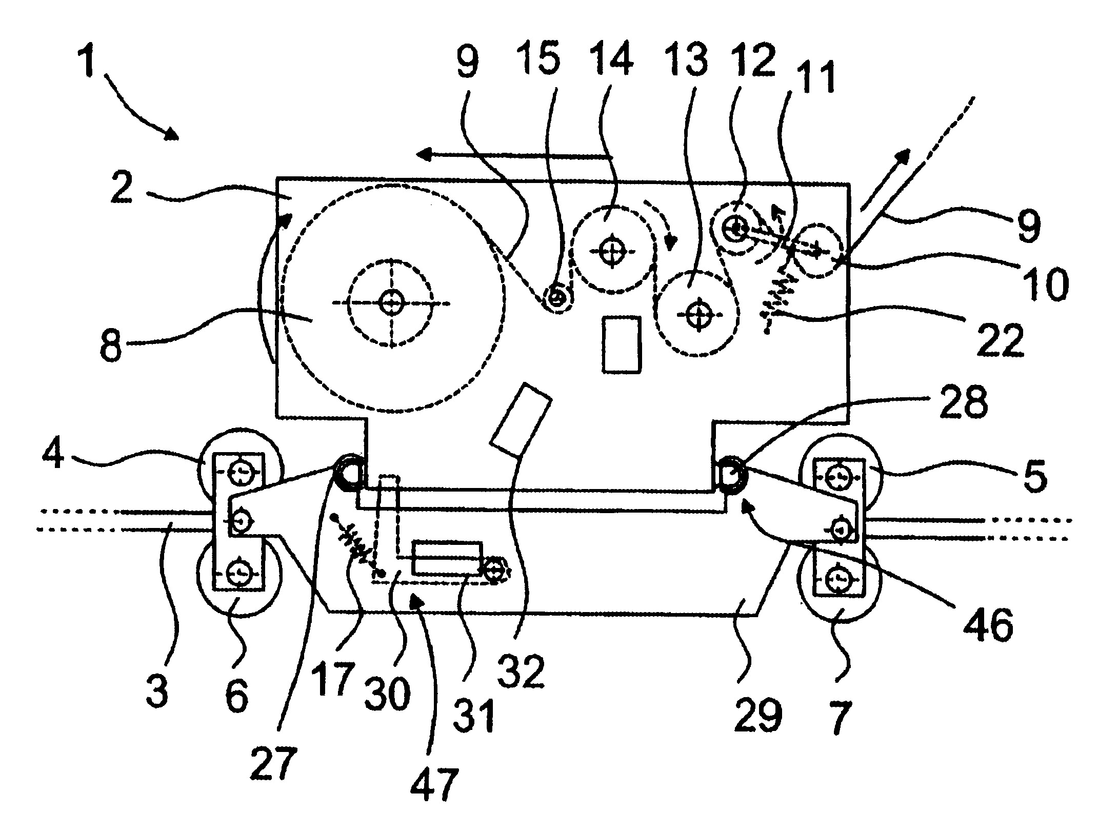
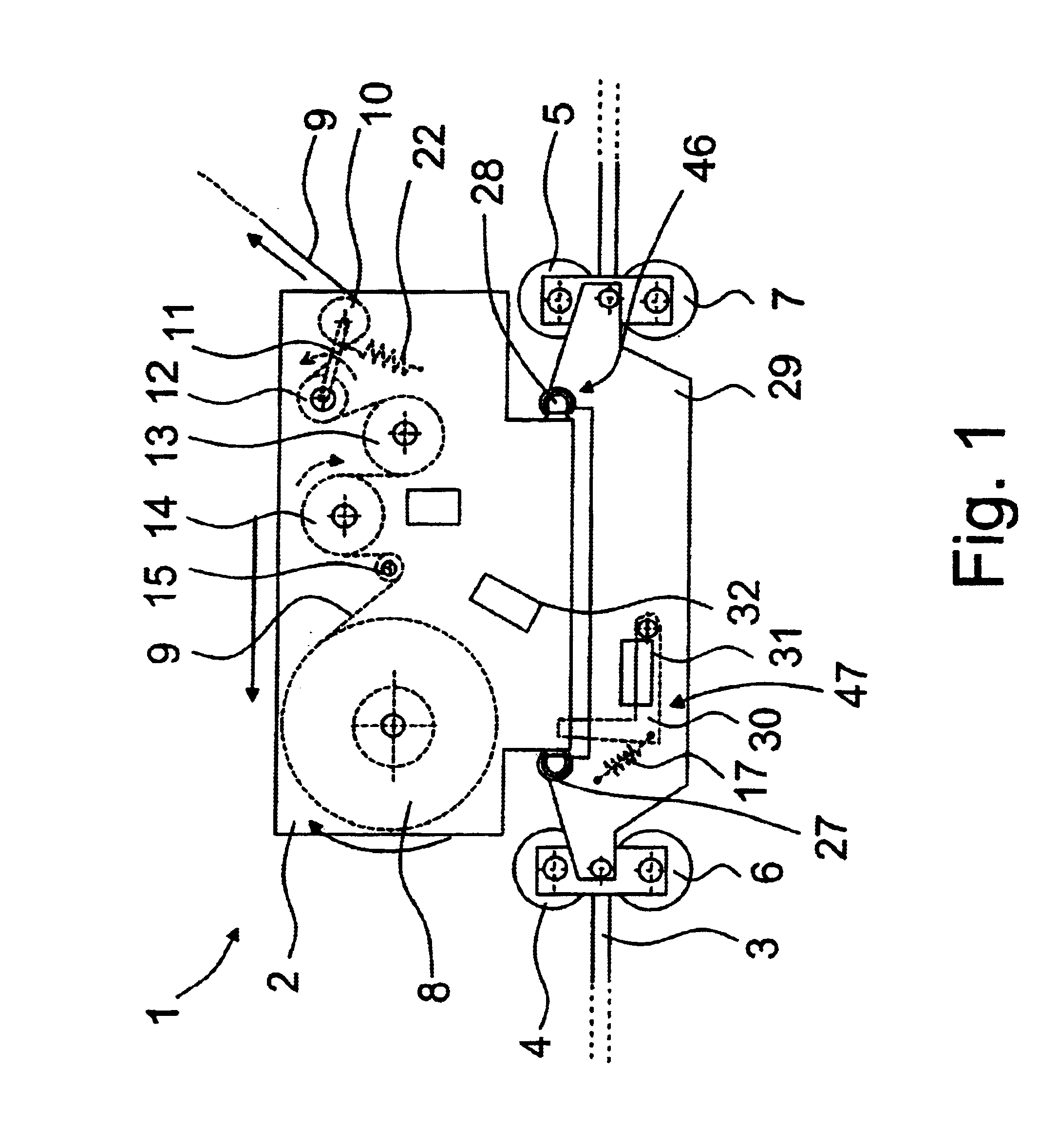
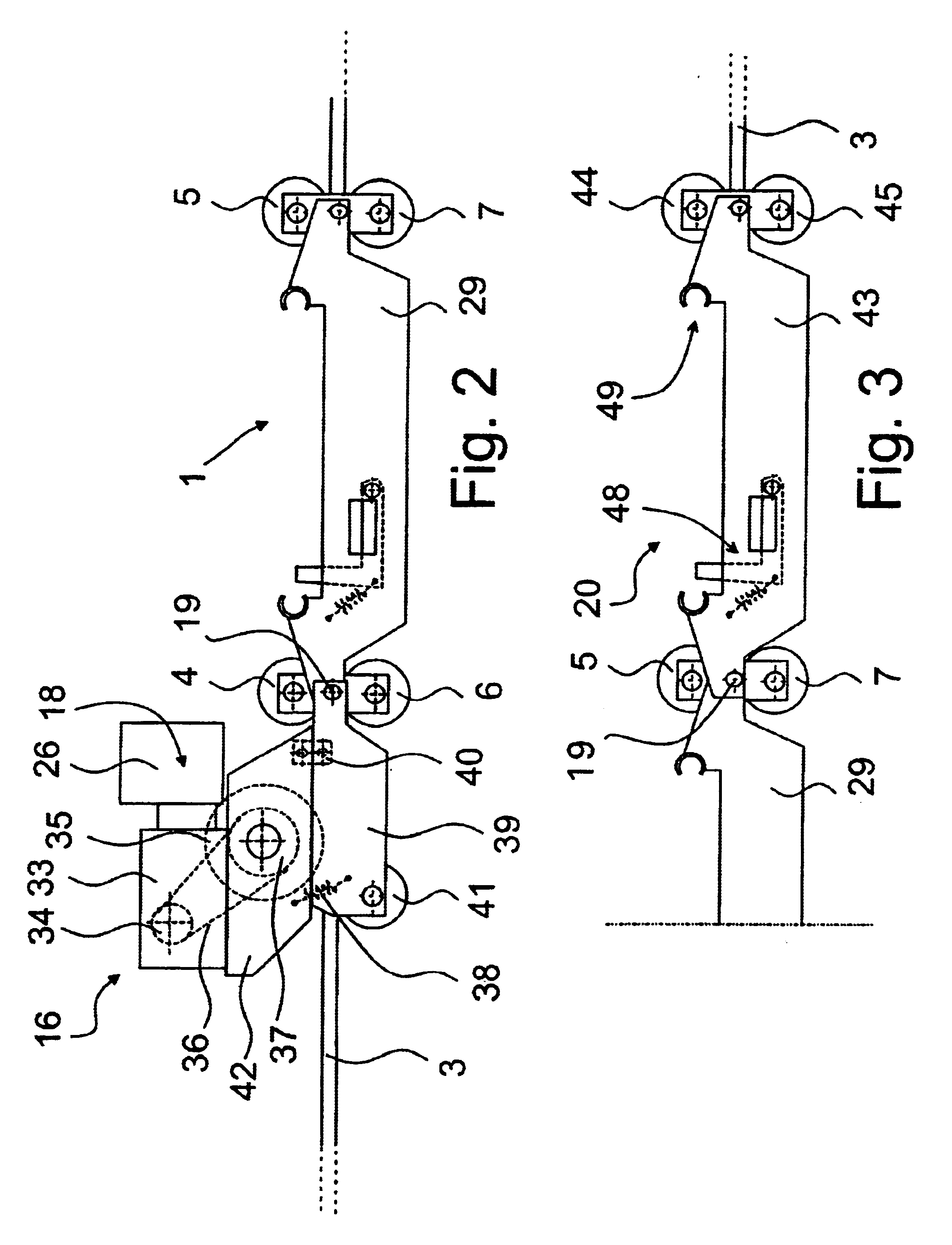
FIG. 1 shows the principle of operation of the film feeding device 1, and in this description, the device 1 will also be called a carriage and the feeding means 10, 12, 13, 14, 15 will also be called guide rolls. The carriage 1 and the guide rolls are shown in a reduced schematic view to illustrate the operation. FIG. 1 shows a situation, in which the film 9 to be fed is suitably tense, wherein the tension of the film is given or higher than that, and it is fed from a film roll 8 forward and further around a piece to be wrapped. The end of the film 9 is attached to the piece, wherein when the carriage 1 moves, the film 9 is simultaneously tightened by the effect of the guide rolls and is unwound from the film roll 8.

One phenomenon in the wrapping device is that the quantity of film to be supplied from the film roll varies each time at different locations of the circular tract, because the carriage is not continuously at the same distance from the piece. At some points, the distance ...


PUM

PropertyMeasurementUnit
Circumferenceaaaaaaaaaa
Timeaaaaaaaaaa
Tensionaaaaaaaaaa

Abstract

A wrapping device provides at least a circular track structure which forms a closed track, and a film feeding device which is arranged to circulate along the track and to feed a film around a piece to be wrapped. The film feeding device includes a frame structure with a rotatable film roll and a feeding mechanism through which the film is arranged to be fed at a desired film tension. The frame structure can be disconnected from and reconnected to the film feeding device for the change of the film roll, and for the change of the film roll, the wrapping device also includes an automatic change system for the change of the frame structure. The frame structure is an integrated unit which can be independently disconnected from and reconnected to the film feeding device. The carriage device of the wrapping device is intended to carry along the film feeding device, and it includes several carriages placed one after the other and coupled to each other, wherein at least one the frame structure is placed or can be placed in one or more carriages.

Description

FIELD OF THE INVENTIONThe invention relates to a wrapping device. The invention also relates to a film feeding device. The invention also relates to a carriage device for a wrapping device.BACKGROUND OF THE INVENTIONFor the wrapping of various pieces, for example coils, wrapping devices known as such are used to perform the wrapping by means of a wrapping film, preferably a thin and transparent stretch film made of plastic. The film roll is normally fitted in film feeding means, which are further placed in a carriage moving along a circular structure and a track formed therein, either around the whole piece or passing through an opening in the central line of the piece.One wrapping device is disclosed in EP 0 936 142 A2, or corresponding U.S. Pat. No. 6,192,653. If the film is slackened, the film roll can rotate in the opposite direction and the film is rewound on the film roll. Another device is shown in EP 0 936 141 B1, in which the film roll is rotated by means of a motor. One kn...

Claims


Application Information

Patent Timeline
IPC IPC(8): B65B41/00B65B41/16B65B11/00B65B11/02B65H16/02B65H19/10B65H19/18B65H23/188
CPCB65B41/16B65B11/00B65H2402/60
Inventor MAKI-RAHKOLA, HANNUMAKI-RAHKOLA, JARITUOMIRANTA, TAPIO
Owner PESMEL
Learn More