
Motor in wheel electric drive system

a technology of electric drive system and motor, which is applied in the direction of electric propulsion mounting, electric devices, transportation and packaging, etc., can solve the problems of reducing the ability of the vehicle, wasting energy and expensive maintenance and/or repair, and restricting the amount of available spa

Inactive Publication Date: 2005-02-08
LEKTROHLDGS
View PDF9 Cites 21 Cited by
  • Summary
  • Abstract
  • Description
  • Claims
  • Application Information

AI Technical Summary

Benefits of technology

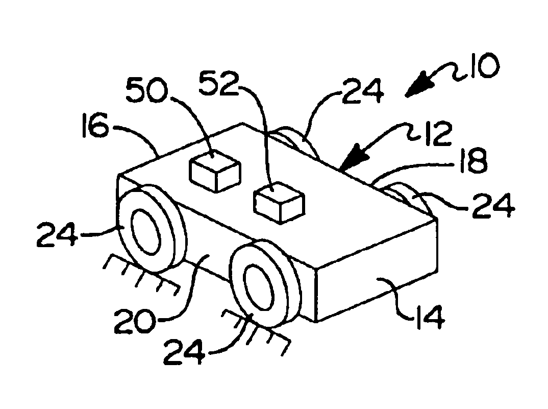
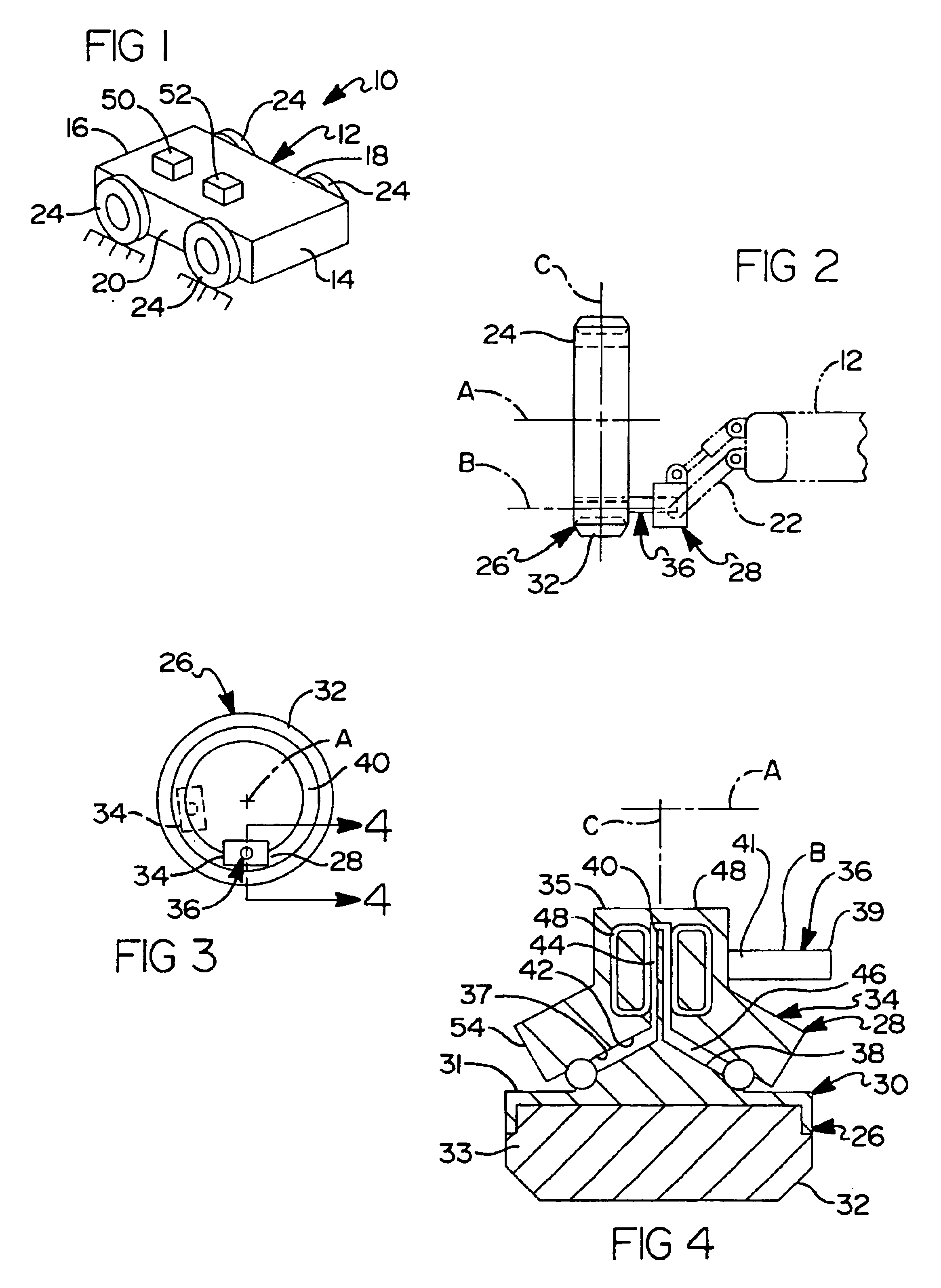
It is an object of this invention to provide an orbital wheel system that provides the means to dynamically control vehicle height, tilt, pitch and wheelbase with or without propulsion capability. In a specific embodiment, the present invention provides an electric drive system for a motor vehicle, which drive system is drivingly connected to the inner rim of at least one, and if desired, the inner rim of each of the respective vehicle wheels and which eliminates conventional chassis mounted power systems, drive trains and hub-mounted wheel-axle suspension systems.
Desirably, the present invention provides a variable height, variable tilt, variable wheelbase, four wheel drive, four wheel steer, fully electronically integrated hybrid rolling chassis with active suspension, enhanced acceleration, regenerative braking, and a steering arduous of almost zero.

Problems solved by technology

However, the EV has met with market resistance in that the battery pack therefor is heavy—cutting down on the ability of the vehicle to accelerate rapidly, is large in size—restricting the amount of available space for transporting passengers or goods, and must be recharged frequently—cutting down on the length of the trip and / or limiting its use to short trips and / or restricting its use to large cities where recharging stations are available.
Further, in its current form, the motor vehicle incorporates numerous mechanical connections that are wasteful of energy and expensive to maintain and / or repair.

Method used


Image

  • Motor in wheel electric drive system
  • Motor in wheel electric drive system
  • Motor in wheel electric drive system

Examples


second embodiment

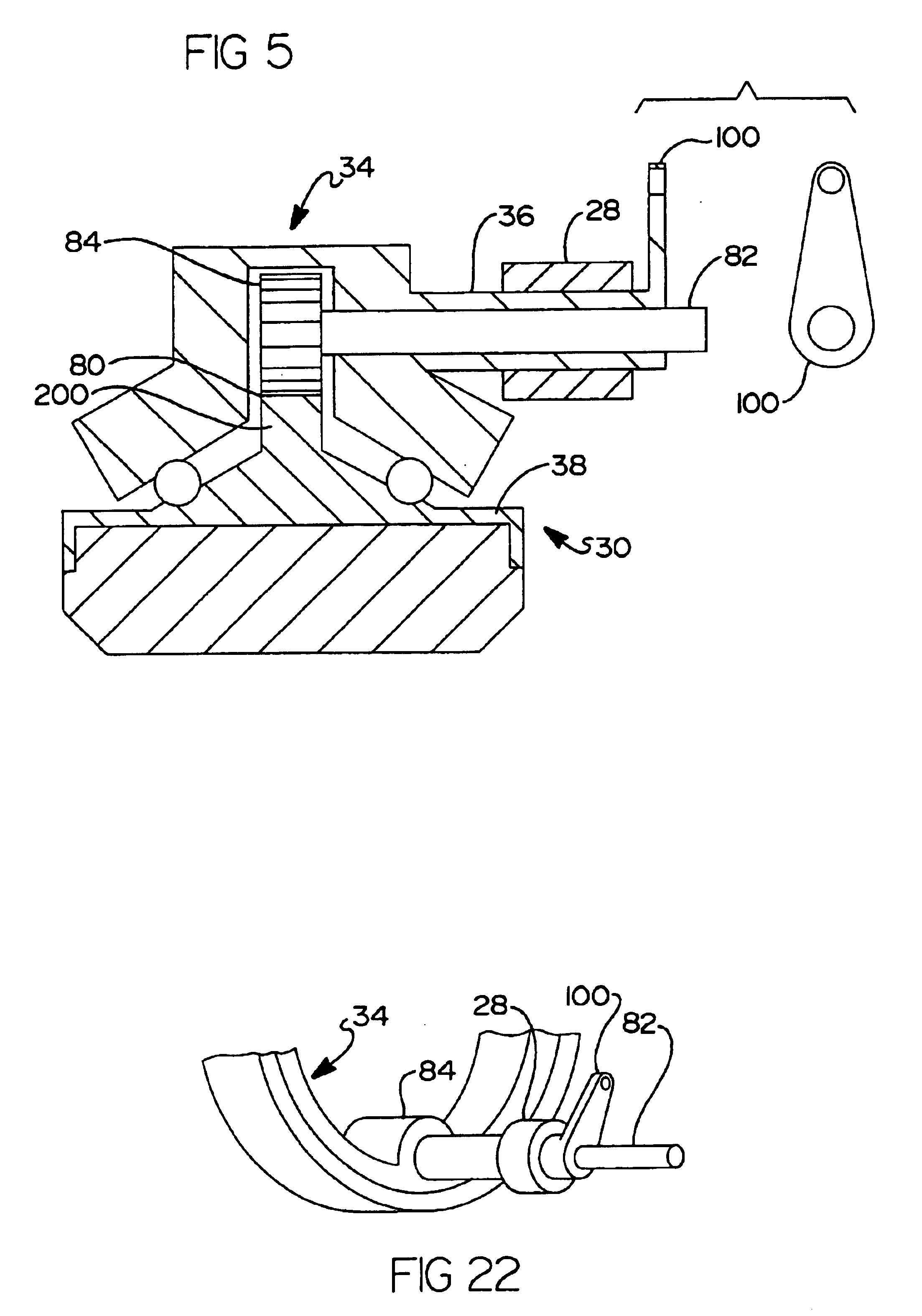
In an electrical motor in wheel arrangement according to this invention, as shown in FIG. 6, the rotor 30 includes a continuous string of permanent magnets 56 and the stator 34 includes a group of pairs of closely packed electrically energizable closed circuit electrical coils or windings 58. The magnets 56 are disposed in each angled face of the V-shaped surface 38 of the rotor 30 and circumferentially arranged in a Hallbach array so that the magnetic orientation of each magnet is at right angles to the magnet adjacent thereto. As the permanent magnet array passes over the coil pairs 58 an electric current is developed in the coils that in turn generates an opposing electromagnetic field that repels the magnet array thus creating a levitating force that supports the rotor 30 in spaced relation from the stator 34.

Alternatively, it is to be understood that the array of permanent magnets could be mounted in the stator and the electrical coils disposed in the rotor, or that the V-shape...


PUM


Abstract

A vehicle is powered by an electric linear induction motor (LIM) in at least one of the vehicle wheels and the height from the ground and / or wheelbase changed by the wheel structure and its connection to the vehicle chassis. The LIM is disposed radially outwardly from the wheel axis of rotation and comprises a stator having an elelctrically energizable propulsion coil circumposed by a rotor. A stator shaft connects the stator to the vehicle chassis and the stator and associated shaft are fixedly-connected and angulary orbited about the inner diameter of the rotor whereby to change the height of the vehicle chassis from the ground or the wheelbase of the vehicle. The rotor is supported for rotation about the stator by bearings, or by magnetic levitation, as provided by a ring of permanent magnets in the rotor disposed in juxtaposition with an electrically energizable levitation coil in the stator.

Description

BACKGROUND OF THE INVENTION1. Field of the InventionThis invention relates generally to improvements in wheeled vehicles of the type having an electric powered, motor in-wheel drive systems, and preferably applicable to hybrid power systems, for propelling the vehicle. In particular, the wheeled vehicle according to this invention includes a combined brushless DC linear induction motor (LIM) vehicle propulsion or other motor-driven propulsion system and a wheel-axle structure, which enables the wheelbase and tilt of the vehicle chassis to be dynamically changed during propulsion of the vehicle.2. Related ArtElectric vehicles and drive systems for vehicles are known. Electrically powered vehicles (“EV's”) are similar to vehicles powered by an internal combustion engine and typically include a chassis for supporting the power system (i.e., the fuel cell, battery, etc.), a drive train and a suspension system, the suspension system connecting several axle and wheel assemblies to the dri...

Claims


Application Information

Patent Timeline
Patent Type & Authority Patents(United States)
IPC IPC(8): B60K7/00H02K41/025H02K7/14B60K17/04H02K7/08
CPCB60K7/0007B60K17/043F16C32/04H02K7/14H02K41/025B60K2007/0038B60K2007/0061B60K2007/0092B60L2200/26H02K2201/15Y02T10/641B60L2220/46Y02T10/64
Inventor PRUCHER, BRYAN P.
Owner LEKTROHLDGS
Learn More