Tangential stress reduction system in a loudspeaker suspension

Inactive Publication Date: 2005-02-08
HARMAN INT IND INC
View PDF10 Cites 28 Cited by
  • Summary
  • Abstract
  • Description
  • Claims
  • Application Information

AI Technical Summary

Benefits of technology

The invention provides designs for suspension elements that, in the case of the surround, increases the amount of excursion and linearity of the diaphragm and thereby improves the performance of the speaker. The design of the suspension elements minimizes the stress on the suspension elements by incorporating various geometric designs into the suspension elements that allow the suspension elements to stretch more easily. The design is incorporated in to the suspension elements without modifying the perimeter size of the

Problems solved by technology

Employing bigger suspension elements, is not, however, a viable solution in a smaller speaker design since the size of the diaphragm must be significantly red

Method used


Image

  • Tangential stress reduction system in a loudspeaker suspension
  • Tangential stress reduction system in a loudspeaker suspension
  • Tangential stress reduction system in a loudspeaker suspension

Examples


Embodiment Construction

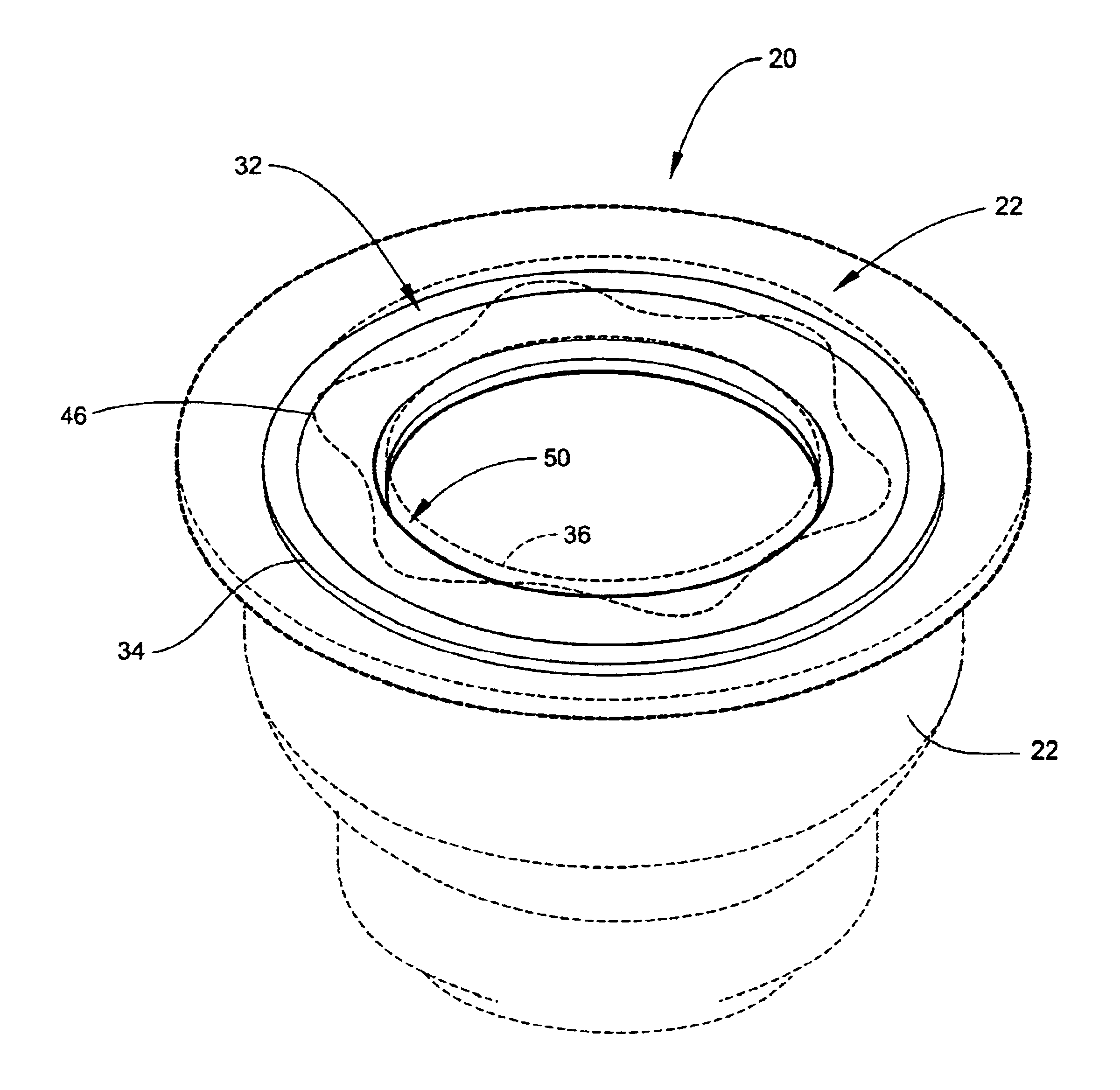
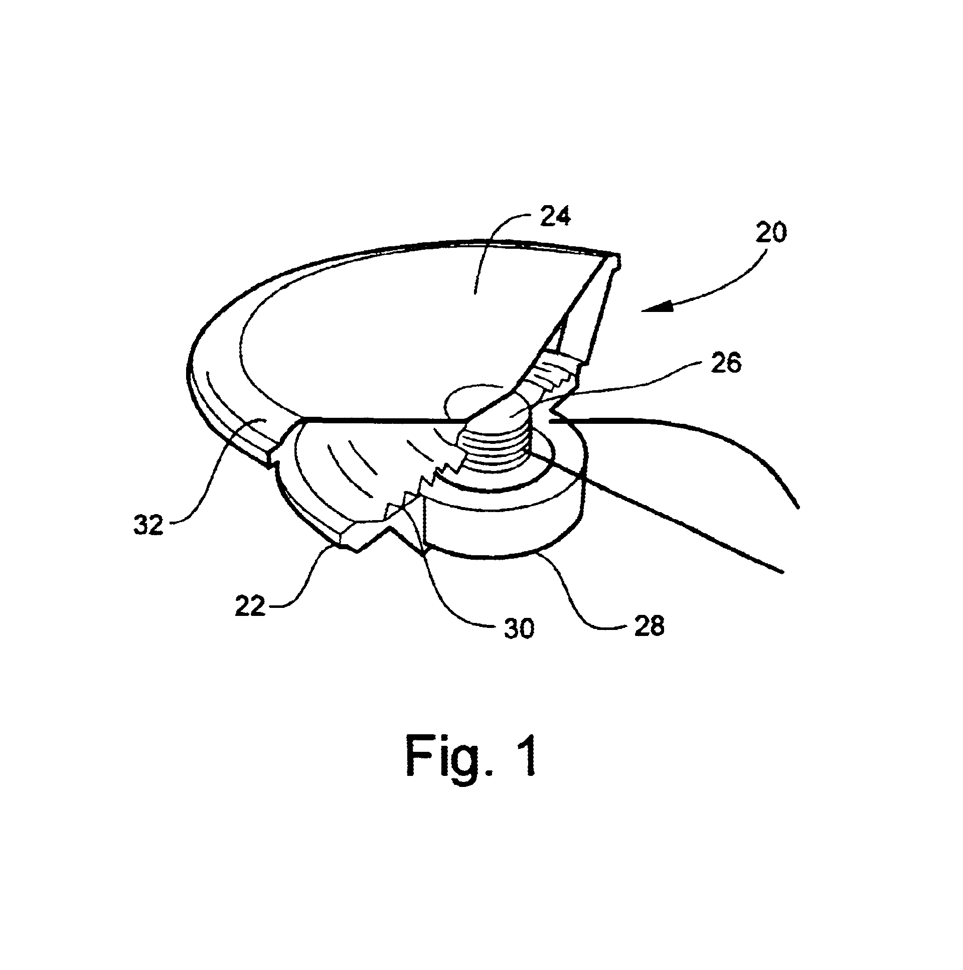
FIG. 1 is a cut away perspective view of a speaker 20, which illustrates the general construction of a traditional speaker 20. A speaker 20 generally includes, among other things, a frame 22, a diaphragm 24, a voice coil 26, a magnet 28, a spider 30 and a surround 32.

The voice coil 26 is attached to the underside of the diaphragm 24. The voice coil 26 and diaphragm 24 are attached to the frame 22 via a suspension system, which generally comprises two suspension elements, the spider 30 and the surround 32. The spider 30 is attached to both the frame 22 and the voice coil 26. The spider 30 is attached to the voice coil 26 in manner that holds the voice coil 28 in position, yet allows the voice coil 26 to freely move up and down. Similarly, the diaphragm 24 is attached to the frame 22 via a surround 32. Alternatively, the surround 32 may be attached to a cylinder (not shown) that is in turn attached to the diaphragm 24. In this regard, U.S. patent application Ser. No. 09 / 346,954, filed...


PUM


Abstract

The invention is a suspension element having an outer edge and an inner edge. The suspension element, such as a spider or surround, varies in shape along at least a portion of the suspension element to help relieve both the radial and tangential stress placed on the suspension element when it is stretched. The shape employed in the suspension element allows the suspension element to stretch more easily, creating a higher performance speaker of the same size by increasing the diaphragm excursion and voice coil movement.

Description

BACKGROUND OF THE INVENTION1. Field of the InventionThis invention relates to the reduction of tangential and radial stress in a suspension element of a loudspeaker transducer. In this invention, the suspension element, such as a surround or spider, is designed to increase its ability to expand in both the radial and tangential directions.2. Related ArtSound reproduction devices such as loudspeakers are utilized in a broad range of applications in many distinct fields of technology, including both the consumer and industrial fields. Sound reproduction devices utilize a combination of mechanical and electrical components to convert electrical signals, representative of the sound, into mechanical energy that produces sound waves in an ambient sound field corresponding to the electrical signal. Thus, variations of electric energy are converted into corresponding variations of acoustic energy, i.e., sound.Traditional speakers convert the electric energy to sound with one or more drivers...

Claims


Application Information

Patent Timeline
IPC IPC(8): G10K13/00H04R7/00H04R7/20
CPCG10K13/00H04R9/043H04R7/20H04R2307/207
Inventor STEAD, BRENDONWILLIAMSON, CLAYTON C.TRAINER, MARK
Owner HARMAN INT IND INC
Why Eureka
Try Eureka