Work carrier changeover device for machine tools

a technology for changing the carrier and machine tools, which is applied in the direction of maintenance and safety accessories, furnace components, lighting and heating apparatuses, etc. it can solve the problems of affecting the machining at the machining station, occupying a large space at the turning station, and generally being unable to attach to a standard machine, etc., and achieves convenient retrofitting of machines, reliable decoupling, and positive retention.

Inactive Publication Date: 2005-02-08
MASCHFAB BERTHOLD HERMLE
View PDF12 Cites 9 Cited by
  • Summary
  • Abstract
  • Description
  • Claims
  • Application Information

AI Technical Summary

Benefits of technology

A problem of the present invention is to create a work carrier changeover device which provides good decoupling between machining station and tooling station and good accessibility to the machining station, with a simple and cost-effective design which permits rapid work carrier changeover and may easily be retrofitted to standard machines.
The benefits of the solution according to the invention are in particular that, because of the horizontally pivotable swivel arm with rotatably mounted coupling element, only one mechanical sub-assembly is required for feeding and changeover of the swivelling work carrier and pallets. The coupling element is not attached rigidly to the machine, but instead is mounted on a swivel arm which is independent of the machine, thereby ensuring on the one hand easy retrofitting capability and on the other hand good decoupling between machine and tooling station. The working area of the machine tool remains readily accessible, since the swivel arm may be swivelled away. Due to the superposition of a swivelling and a rotary movement, it is possible for the coupling element to traverse along a predetermined, optimised, curved path. This makes possible a rapid changeover of pallets, even where space is restricted.
The separate arrangement of the tooling station makes possible automatic loading and unloading of pallets at this point using a feed unit located at the setting-up station, for example a conveyor belt.
The coupling element and / or the swivel arm are provided with a vertical lifting device, wherein the coupling points of the coupling element are formed by a vertical lift for coupling to the work carriers from below. The coupling points of the coupling element are preferably provided with non-positive or positive retaining means for releasable fixing of work carriers, for example with an hydraulic releasing and clamping system, to ensure safe changeover of the work carriers and workpieces, some of which are very heavy. With smaller work carriers, a positive means of retention may be adequate.
The tooling station is designed as an independent station, separate from the machine tool, thereby ensuring on the one hand reliable decoupling, and on the other hand easy retrofitting of machines.
The tooling station is expediently provided with a swivel door assembly, which is located on a wall forming an outer space in front of the access zone to the machining station, wherein in a first operating position the tooling station is integrated in this outer space, and in a second operating position the tooling station is separated from this outer space. This enables the operator, in the one operating position, to reach the tooling station too from the access zone to the machining station. In the second operating position, the swivel door assembly closes between the machining station and the tooling station, so as to shield the working area from water spray, enabling the pallet to be cleaned in the tooling station for example using compressed air or spray.

Problems solved by technology

Besides the poor accessibility to the working area due to the direct mounting of the changeover device on the machine, the traversing station takes up a large amount of space.
Subsequent attachment to a standard machine is generally impossible.
Attachment to the machine brings about inadequate decoupling between machining station and setting-up station so that there is a danger that, during the setting-up process, i.e. during the loading of the work carrier with new workpieces at the setting-up station, machining at the machining station is adversely affected.
A further drawback lies in the fact that, due to the transfer by means of swivel and linear movements, the work carrier changeover takes an unsatisfactory length of time.
In this case, subsequent attachment to a standard machine would mean even greater expense, which would make such attachment virtually impossible.
In actual-time parallel tooling, the integration of tooling station and machining station means that vibrations and forces are transmitted to the machining table, which has a negative effect on the accuracy of machining.
Automatic loading by means of a handling system is therefore even more problematic.
Another drawback is the poor accessibility to the machining station due to the platen shuttle being rigidly attached to the machine.
While this certainly leads to good decoupling of machining station and tooling station, and provides good accessibility to the working area, there is a very high space requirement together with an expensive and cost-intensive design, while the work carrier changeover requires a relatively large amount of time.

Method used


Image

  • Work carrier changeover device for machine tools
  • Work carrier changeover device for machine tools
  • Work carrier changeover device for machine tools

Examples


Embodiment Construction

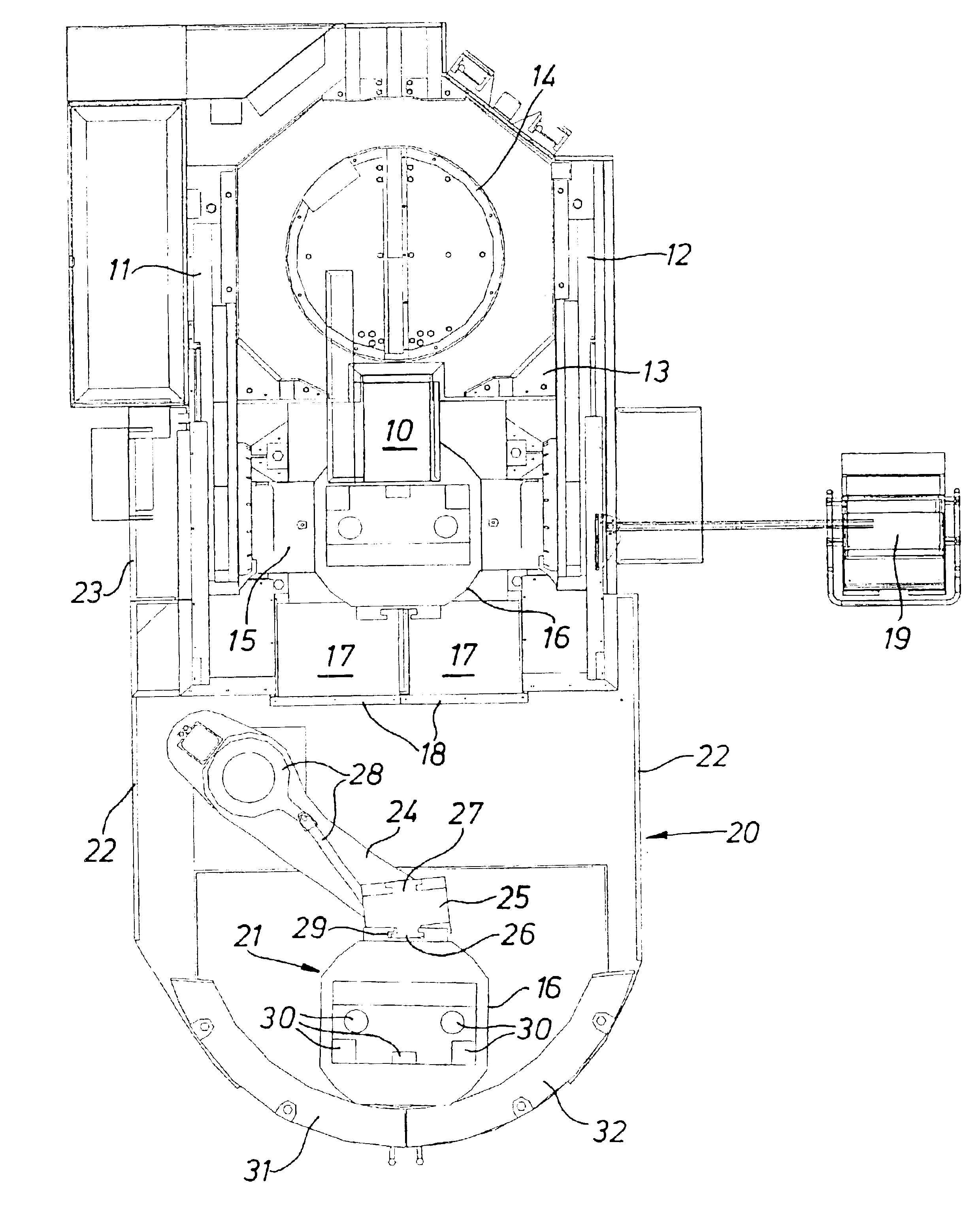
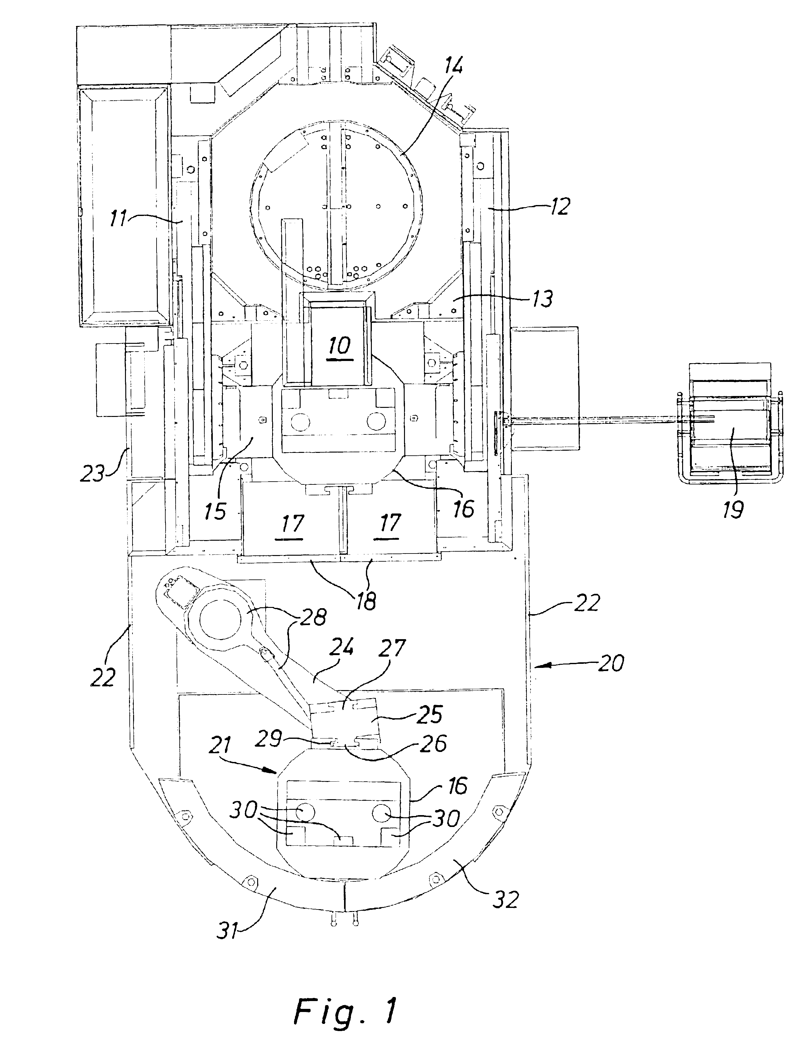
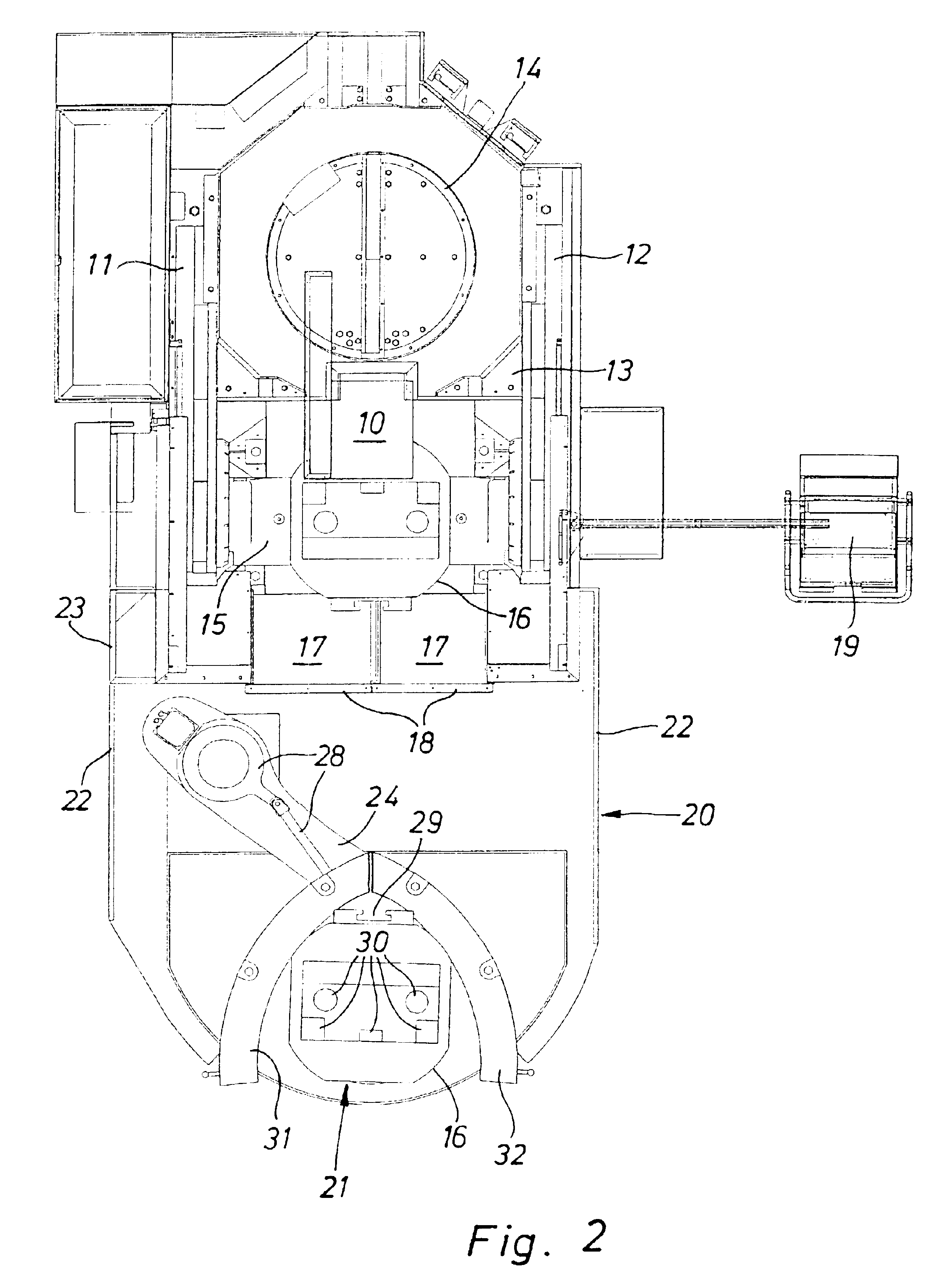
The machine tool shown in the Figures has a vertical spindle nose 10 and is in gantry form. A slide 13 is able to traverse horizontally on two side walls 11, 12 of the machine column. The spindle nose 10 is able to traverse at right-angles and vertically to its front side. Shown schematically in the rear area of the machine column is a tool-change magazine 14. Between the side walls 11, 12 and below the spindle nose 10, a swivelling rotary table is pivotably mounted around a horizontal axis for the direct accommodation of work or to accommodate work carriers in the form of work pallets 16. The access zone 17 in front of the swivelling rotary table 15 forming the machining station may be closed by doors 18 which may be slid sideways or upwards or hinged up. Located at the side of the machine tool is a control console 19 which may be swivelled in and out.

The depicted variant of the machine tools is only an example, i.e. the work carrier changeover device or work pallet changeover devi...


PUM

PropertyMeasurementUnit
movementaaaaaaaaaa
length of timeaaaaaaaaaa
forcesaaaaaaaaaa

Abstract

The invention concerns a work carrier changeover device for machine tools, with a work carrier transfer device for moving the work carrier (16) between a machining station (15) and a tooling station (21). The work carrier transfer device has a coupling element (25) rotatable around a vertical axis and two opposing coupling points (26, 27) for the coupling of work carriers (16). The coupling element (25) is pivotably mounted at free end section of a swivel arm (24) capable of swivelling around a vertical axis.

Description

BACKGROUND OF THE INVENTION1. Technical Field of the InventionThe invention relates to a work carrier changeover device for machine tools, with a work carrier transfer device for moving the work carrier between a machining station and a tooling station, wherein the work carrier transfer device has a coupling element rotatable around a vertical axis and with two opposing coupling points for the coupling of work carriers.2. Prior ArtIn a changeover device of this kind known from EP 0409085 B1, a coupling element for work carriers, capable of rotating through 180°, is located on the machine itself, while a linear work carrier traversing station is also required to bring the work carriers, each provided with workpieces, to the machining station. Besides the poor accessibility to the working area due to the direct mounting of the changeover device on the machine, the traversing station takes up a large amount of space. Subsequent attachment to a standard machine is generally impossible. ...

Claims


Application Information

Patent Timeline
Patent Type & Authority Patents(United States)
IPC IPC(8): B23Q11/08B23Q7/14
CPCB23Q7/1431B23Q11/0891Y10T29/5196
Inventor BERNHARD, FRANZ-XAVERKOHLER, RAINER
Owner MASCHFAB BERTHOLD HERMLE
Why Eureka
Try Eureka