Flow-through media

a technology of flow-through media and support media, which is applied in the direction of biological water/sewage treatment, filtration separation, separation processes, etc., can solve the problems of “dead zone” in the system, weakening the shaft, and allowing bacteria

Inactive Publication Date: 2005-02-08
JRJ HLDG
View PDF37 Cites 21 Cited by
  • Summary
  • Abstract
  • Description
  • Claims
  • Application Information

AI Technical Summary

Benefits of technology

One aspect of the present invention is a flow-through media element having an outer wall defining a truncated conical shape with two open ends and a plurality of internal ribs. The length of the medium element is greater than the largest diameter of both open ends. The internal ribs may extend through the outer wall to create external ribs or separate external ribs may be affixed to ...

Problems solved by technology

One limitation with this design is that the bacteria are allowed to grow and die in a normal life cycle without a cleansing function.
The result is a buildup of dead bacteria carcasses (slough) around the shaft, creating a “dead zone” in the system and a weakening of the shaft.
These shapes, by their basic design, incorporate a “dead zone” at the bottom of the cups where the slough builds up, substantially reducing overall performance of the wastewater treatment system.
Although this type of media does not have a closed end in which bact...

Method used


Image

  • Flow-through media
  • Flow-through media
  • Flow-through media

Examples


Embodiment Construction

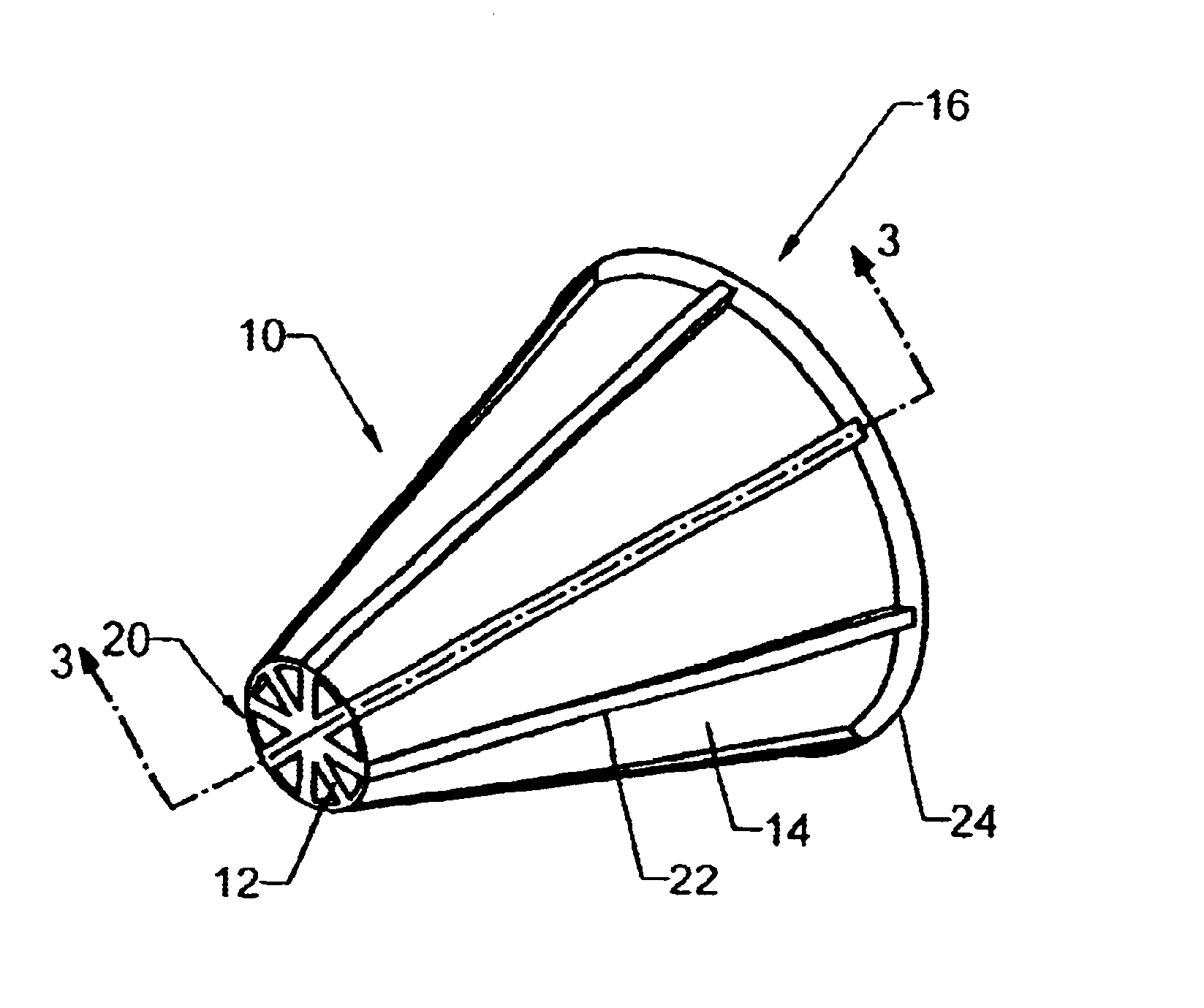
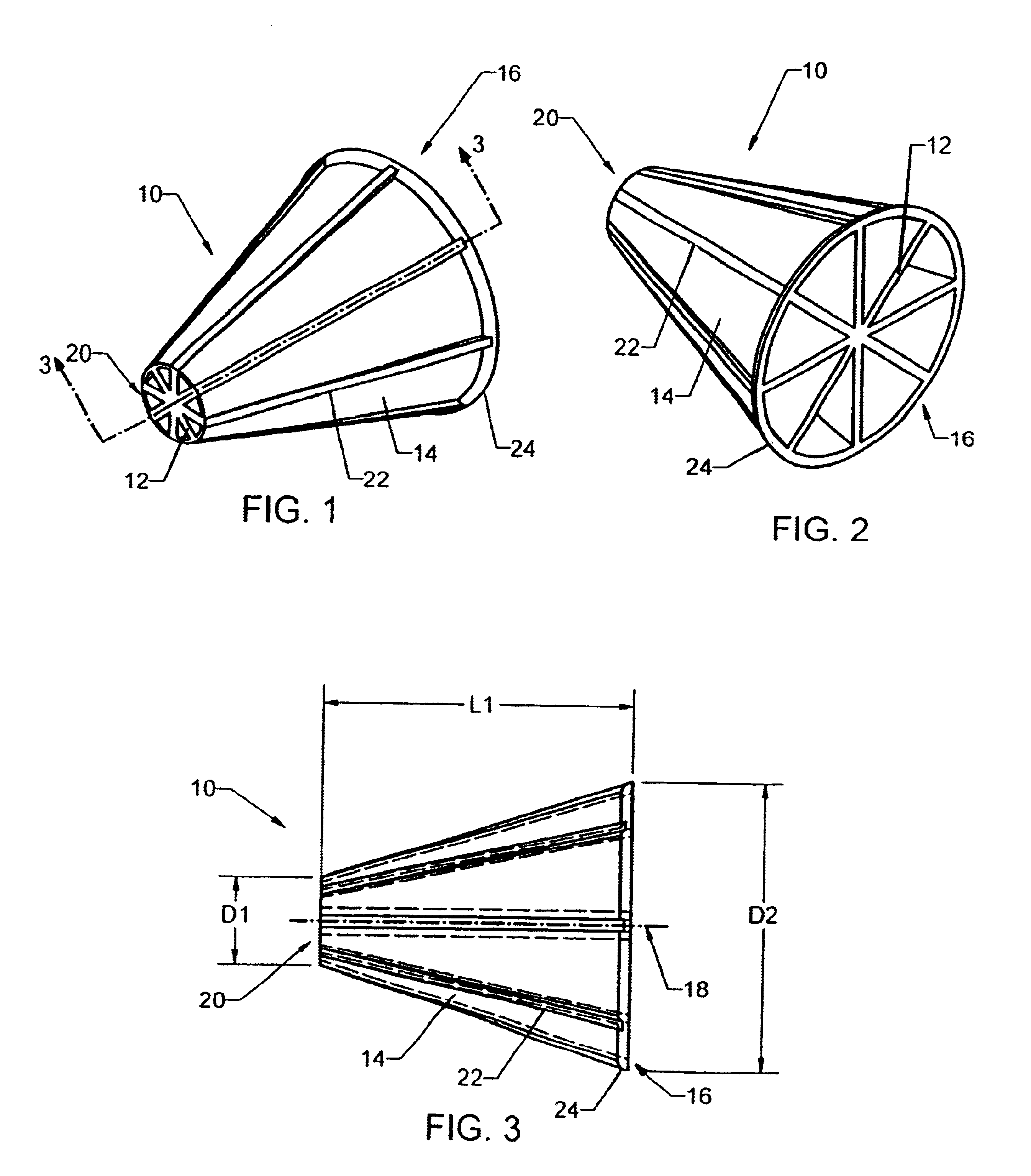
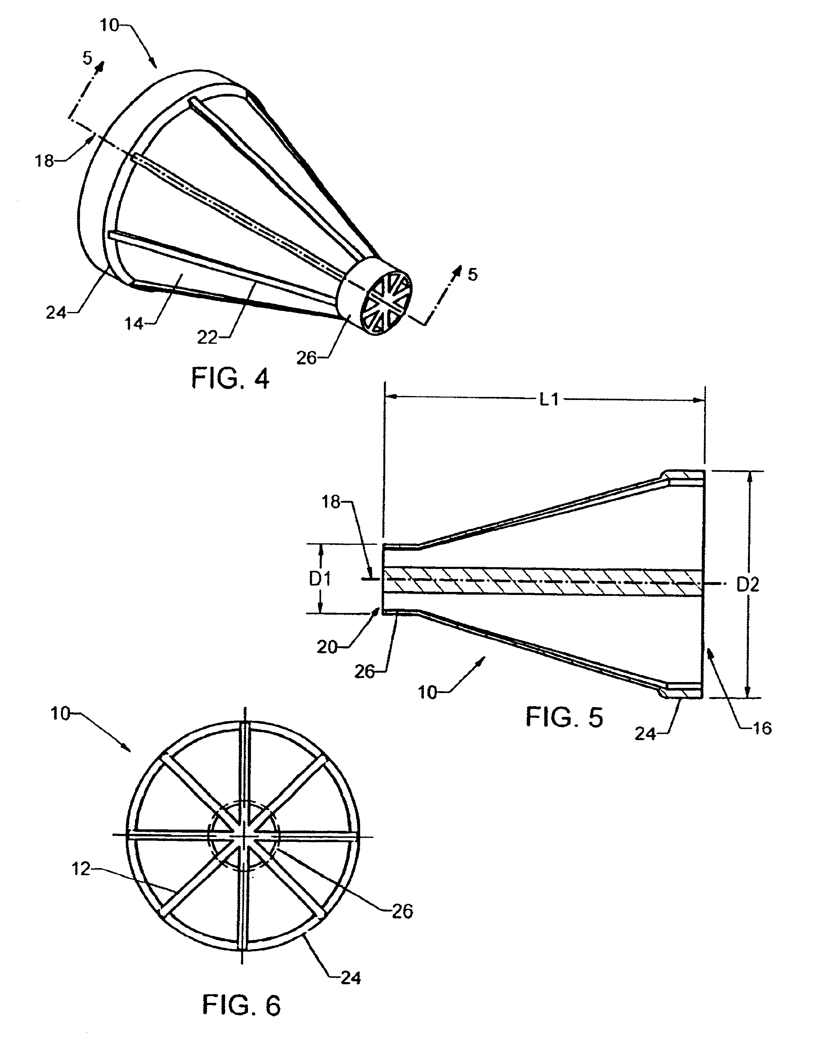
Now with more particular reference to the drawings, FIGS. 1, 2 and 3 show one embodiment of the flow-through media element 10 of the present invention. FIG. 2 shows another perspective view of the embodiment of the media element in FIG. 1. FIG. 3 shows a sectional view taken along line 3—3 of the embodiment of the media element shown in FIG. 1. The outer wall 14 of the media element 10 defines a truncated conical shape having a central longitudinal axis 18. This embodiment contains eight internal ribs 12. The internal ribs 12 extend radially from the central longitudinal axis 18 and adjoin with the outer wall 14 of the media element 10, and extend longitudinally from a first end 20 to a second end 16 of the media element 10. In this embodiment, the internal ribs 12 are equidistant from each other and are of similar length and width.

This embodiment also contains a plurality of external ribs 22 on the outer wall. These external ribs 22 may be continuations of the internal ribs which e...


PUM

PropertyMeasurementUnit
Fractionaaaaaaaaaa
Fractionaaaaaaaaaa
Angleaaaaaaaaaa

Abstract

A flow-through medium for use in a biological digester has a truncated conical shape, a plurality of internal ribs, and optional external ribs. The conical shape of the media creates a venturi-like action for fluid flowing through the media, which increases the tumbling of the media elements against each other and against the wall of the enclosure in which they are contained. Moreover, the conical shape and venturi-like action prevents slough from accumulating within the media elements, allowing it to be washed through the media.
A method of treating sewage effluent includes placing the media elements in an enclosure partially submersed in the effluent and rotating the enclosure to expose the media to the effluent and to a source of oxygen.

Description

BACKGROUND1. Technical FieldThe present invention relates to a method and apparatus for use in the purification of polluted liquids and other effluents. In particular, the present invention relates to bacterial support media and a method for use of such media in the biological treatment of wastewater.2. Background InformationWastewater treatment systems must be capable of converting a stream of wastewater into a condition suitable for discharge into the surrounding ecosystem. Some types of systems contain rotating biological contactors (RBCs), which are used to host aerobic bacteria. The RBCs work to provide those bacteria with a continual supply of all life-supporting ingredients, including food, oxygen and protective housing.Original RBCs consisted of plastic sheets attached to a central shaft. Bacteria would attach themselves onto the plastic sheets, and the bacteria would be exposed to both food and water by rotating the shaft and sheets into a bath of wastewater. As the bacteri...

Claims


Application Information

Patent Timeline
IPC IPC(8): C02F3/08B01J19/30C02F3/10
CPCB01J19/30C02F3/10B01J2219/30226B01J2219/30408Y10S261/72B01J2219/3083C02F3/08B01J2219/30466Y02W10/10
Inventor PETRONE, RICHARD J.
Owner JRJ HLDG
Why Eureka
Try Eureka