Stable oscillator

Inactive Publication Date: 2005-02-08
ANALOG DEVICES INC
View PDF7 Cites 14 Cited by
  • Summary
  • Abstract
  • Description
  • Claims
  • Application Information

AI Technical Summary

Problems solved by technology

Among others, crystal oscillators typically are relatively large and expensive.
One problem with conventional non clocking circuits, however, is their susceptibility to malfunctioning in extreme environme

Method used


Image

  • Stable oscillator
  • Stable oscillator
  • Stable oscillator

Examples


Embodiment Construction

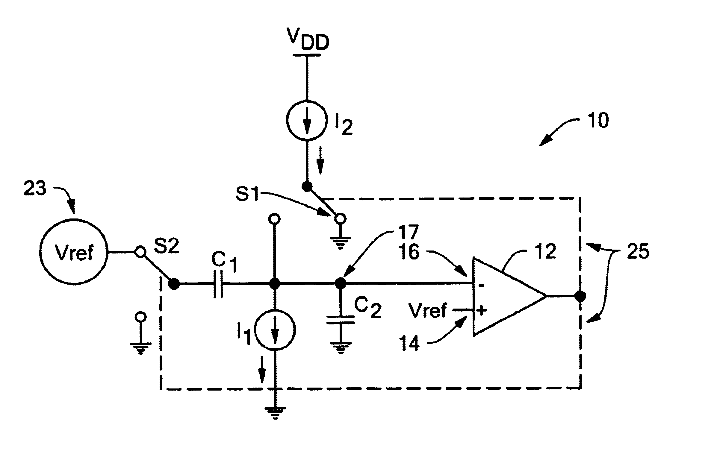
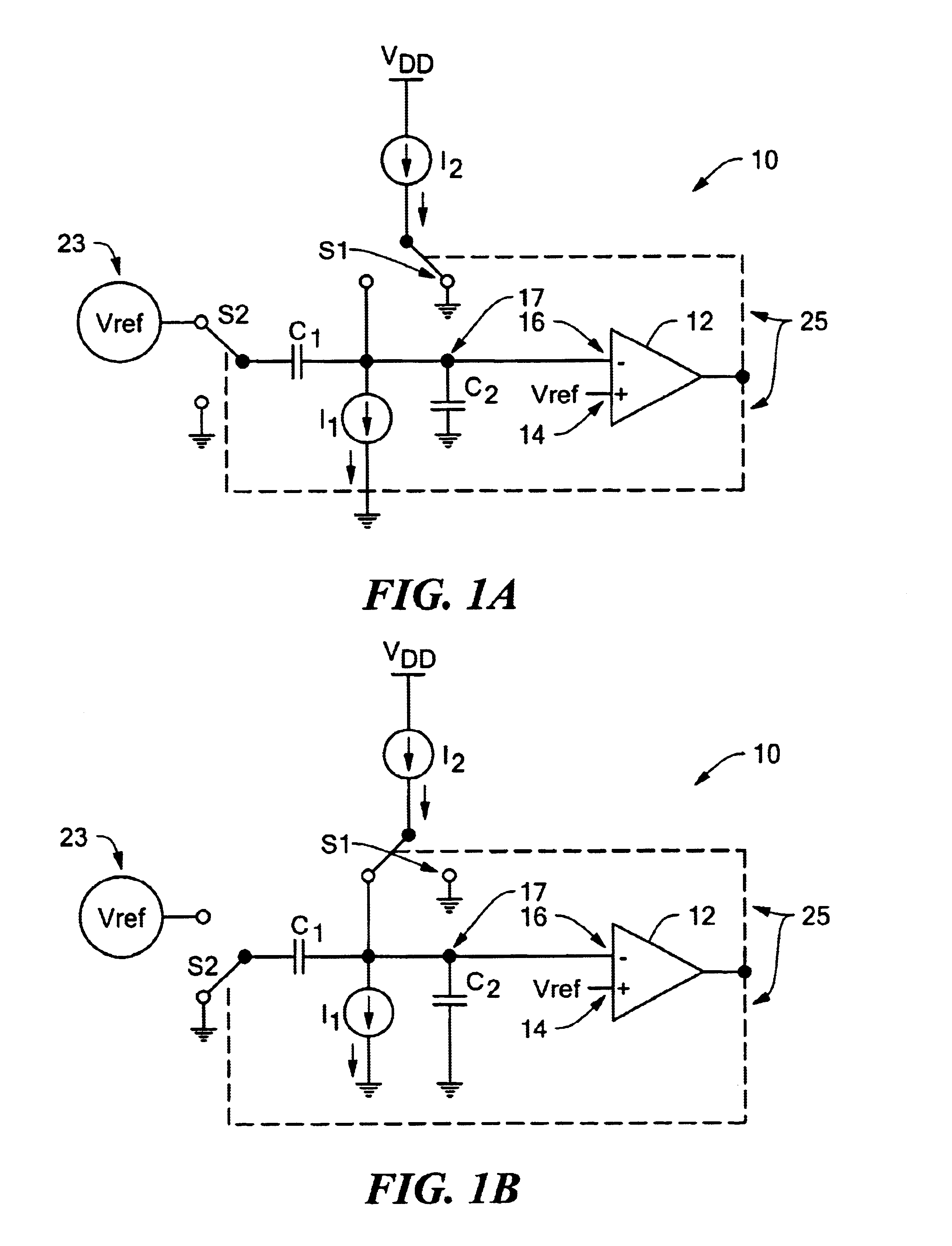
In illustrative embodiments of the invention, an oscillator maintains its output timing signal at a substantially constant frequency by compensating for unintended changes in operating parameters, such as supply voltage and temperature. In addition, the oscillator also compensates for unintended variability in component values, such as transistor circuitry (e.g., NMOS, PMOS, and CMOS circuitry) within reference voltage producing circuitry. Details of various details are discussed below.

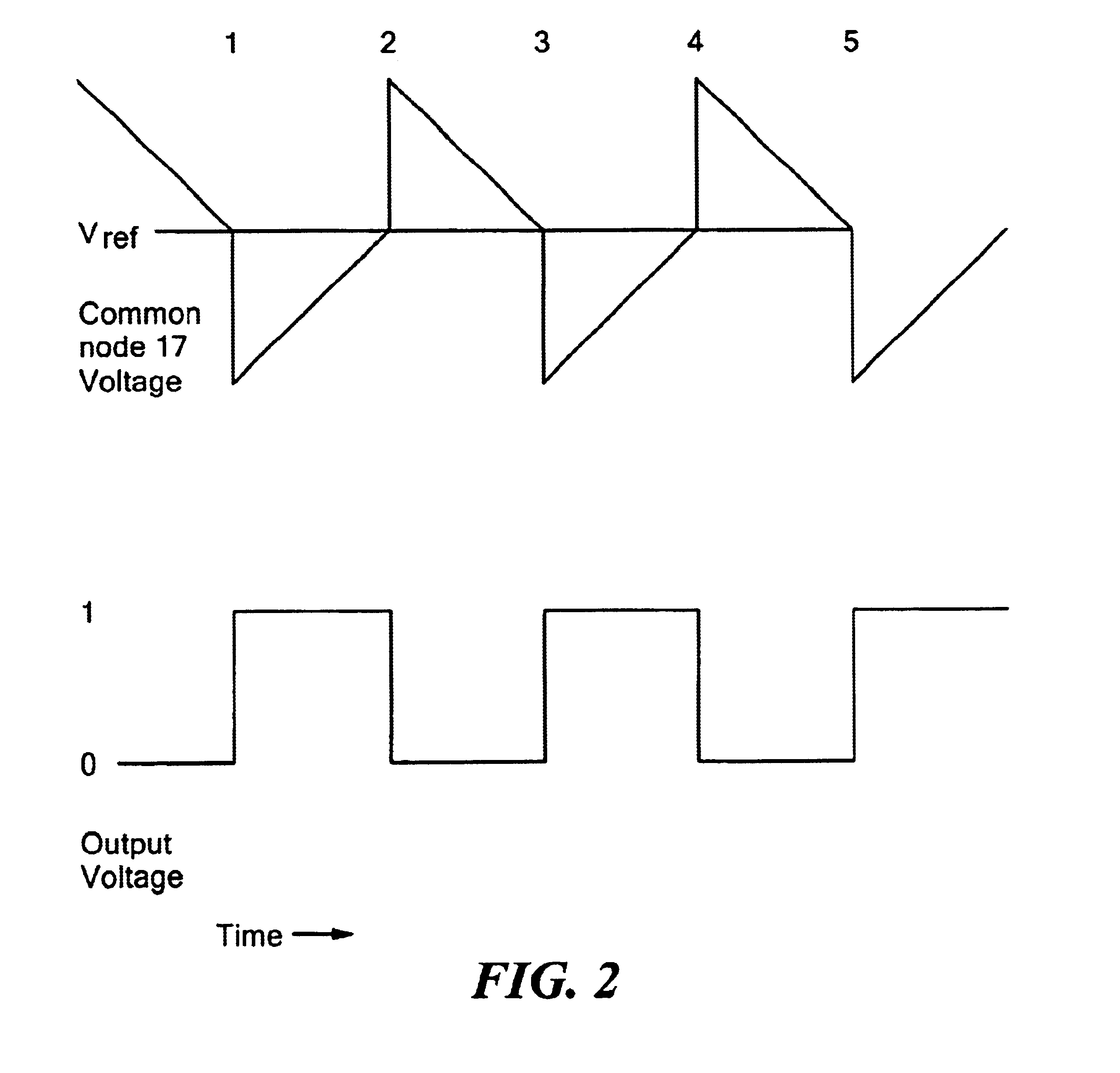
FIGS. 1A and 1B schematically show an oscillator 10 configured in accordance with illustrative embodiments of the invention. FIG. 1A shows the oscillator 10 in a low mode, while FIG. 1B shows the oscillator 10 in a high mode. When in the low mode, the oscillator output generates a logical zero output, while when in the high mode, the oscillator 10 generates a logical one output. Accordingly, in illustrative embodiments, the oscillator 10 generates a precise output clocking signal that alternates betwe...


PUM


Abstract

An oscillator includes a comparator and a variable voltage element. The comparator has a first input set to a reference voltage, a second input, and an output configured to produce an output voltage as a function of the voltages at the first and second inputs. The variable voltage element delivers to the second input a second voltage that is a function of a switched current. The switched current is a function of the reference voltage.

Description

FIELD OF THE INVENTIONThe invention generally relates to electronic clocking circuits and, more particularly, the invention relates to maintaining the accuracy of electronic clocking circuits in uncertain environments.BACKGROUND OF THE INVENTIONElectronic clocking circuits (hereinafter “clocking circuits”) are used in a wide variety of applications. For example, many solid state electronic devices (e.g., microprocessors) operate at a rate set by an internal or external clocking circuit. Accordingly, the accuracy of the clocking signal generated by a clocking circuit generally is critical to the proper operation of the underlying device being clocked. Many devices thus use conventional crystal oscillators to clock their underlying processes.Crystal oscillators have a number of drawbacks. Among others, crystal oscillators typically are relatively large and expensive. Consequently, noncrystal clocking circuits have been developed to provide the same function while crystal being both sm...

Claims


Application Information

Patent Timeline
IPC IPC(8): H03K5/125H03K3/0231H03K3/011H03K5/1252H03K3/00H03K5/08H03K5/00
CPCH03K3/011H03K3/0231H03K5/1252H03K5/08H03K2005/00078
Inventor TOLIVER, CHRISTOPHER M.ENGLISH, STEPHEN T.NESTLER, ERIC G.
Owner ANALOG DEVICES INC
Why Eureka
Try Eureka