Noise filter

a noise filter and noise technology, applied in the field of noise filters, can solve the problems of increasing the frequency of common-mode noise, increasing the noise despite the noise filter, and radiation of electromagnetic noise, and achieve the effect of preventing resonance nois

Inactive Publication Date: 2005-02-08
MURATA MFG CO LTD
View PDF4 Cites 19 Cited by
  • Summary
  • Abstract
  • Description
  • Claims
  • Application Information

AI Technical Summary

Benefits of technology

To overcome the problems described above, preferred embodiments of the present invention provide a small noise filter in which the attenuation ratio for each of the mode signals can be set while preventing resonance noise.

Problems solved by technology

Due to various reasons, common-mode noise (common-mode signal), which causes radiation of electromagnetic noise, disadvantageously flows in these differential lines.
Accordingly, if a noise filter is disposed in a mid-portion of the lines that connect the circuits, noise having a specific frequency often resonates between the noise filter and a peripheral circuit, which increases the noise despite the noise filter.
Thus, the frequency of common-mode noise is also increasing, and the line length between the noise filter and a peripheral component or the line length between a plurality of components is vulnerable to the noise.
Accordingly, in known noise filters, noise cannot be sufficiently eliminated due to the influence of the resonant frequency caused by the reflection, and signal waveforms are distorted.
Thus, in electronic devices using high frequency signals, noise filters that eliminate noise by utilizing reflection loss cannot be effectively used.
It is thus difficult to set the attenuation ratio for each of the mode signals.

Method used


Image

  • Noise filter
  • Noise filter
  • Noise filter

Examples


Embodiment Construction

The present invention is described in detail below with reference to the accompanying drawings through illustration of preferred embodiments.

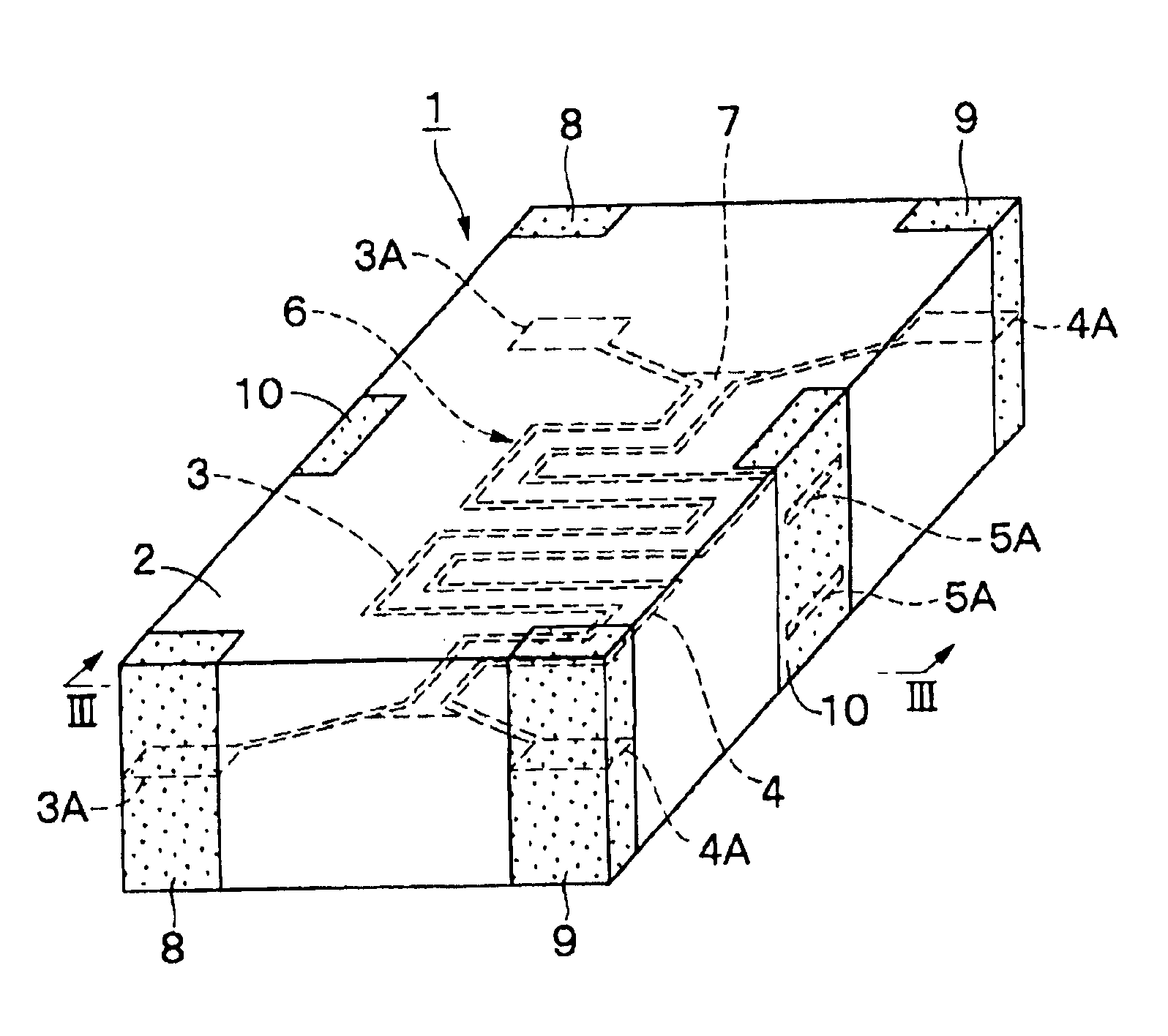
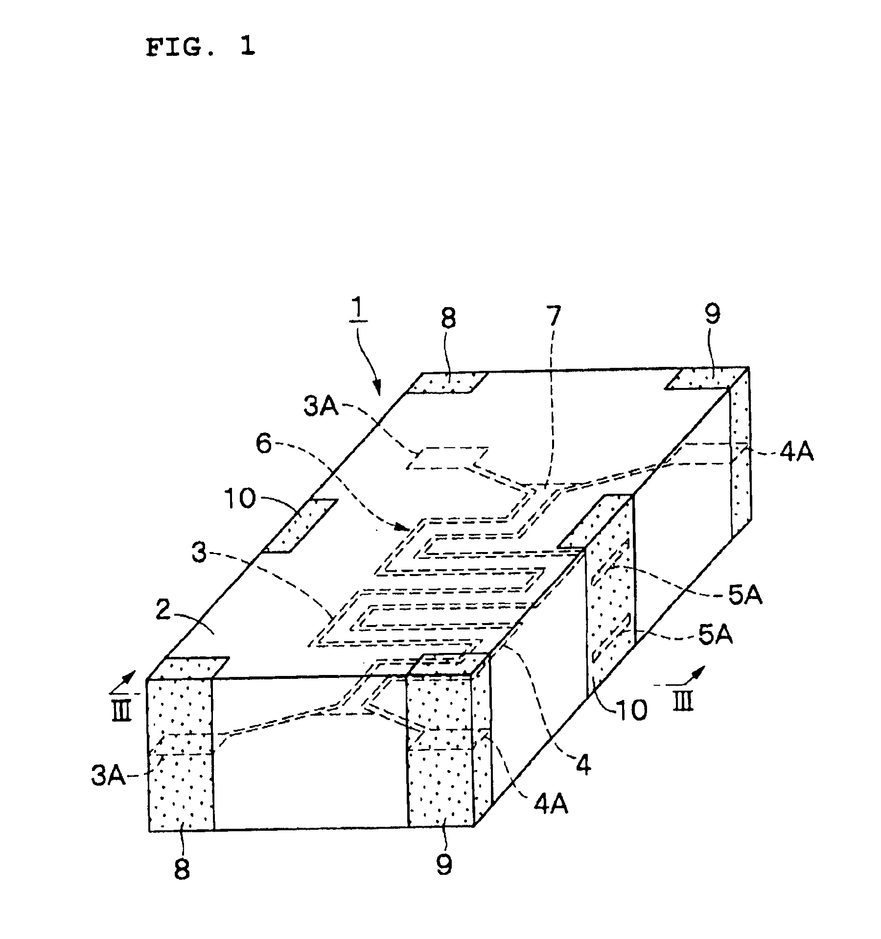
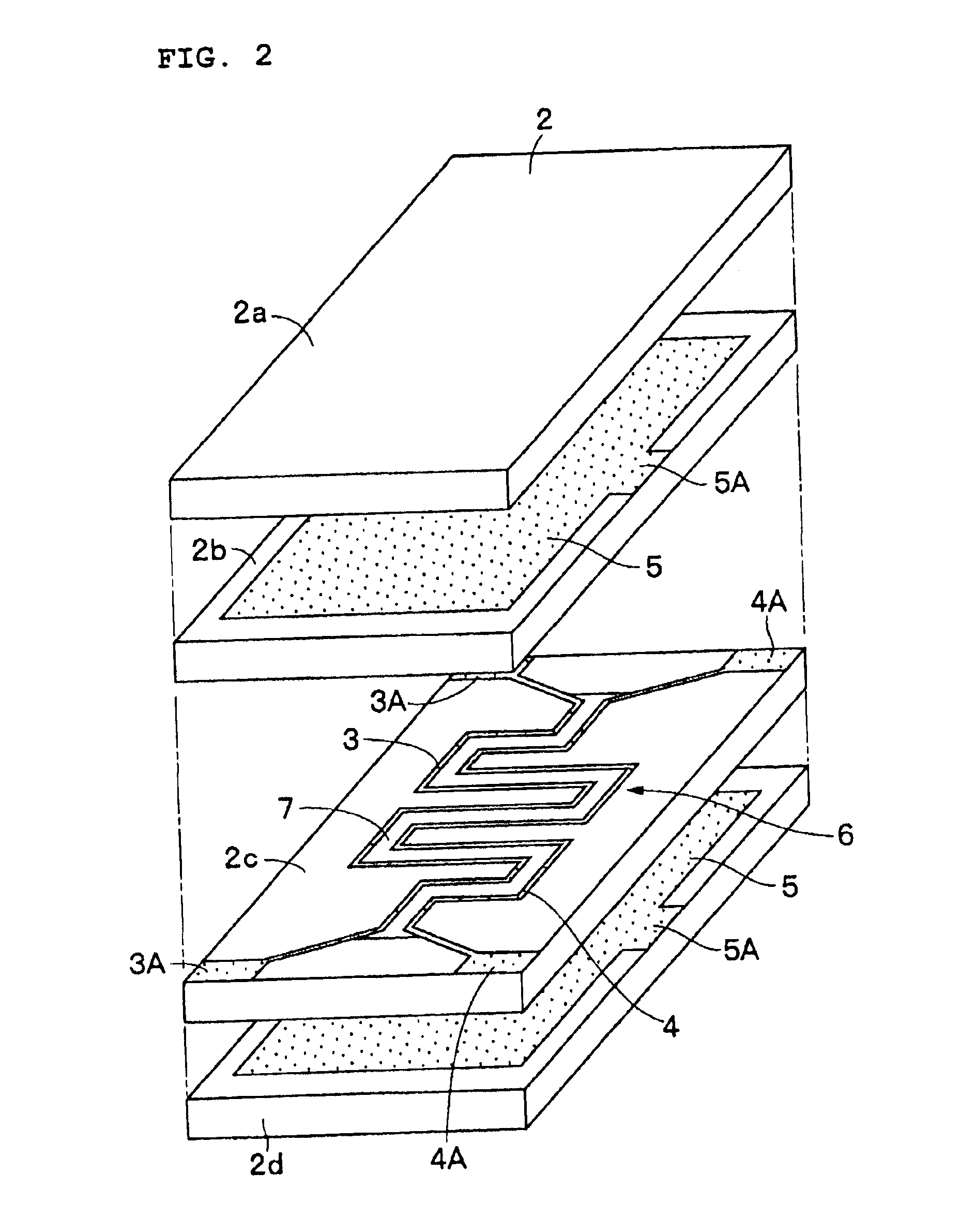
A noise filter 1 according to a first preferred embodiment of the present invention is described below with reference to FIGS. 1 through 9.

The noise filter 1 includes magnetic layers 2a through 2d, signal lines 3 and 4, ground electrodes 5, a dielectric member 7, signal electrode terminals 8 and 9, and ground electrode terminals 10, which are described below.

The magnetic layers 2a through 2d define a laminated unit 2 preferably having the shape of a prism, which serves as an insulating medium to define the outer shape of the noise filter 1. The magnetic layers 2a through 2d, which serve as insulating layers, are formed by laminating four magnetic sheets and then by pressing and firing them. The magnetic layers 2a through 2d are preferably formed in the shape of a flat quadrilateral by using a ceramic material (magnetic material) which exhibits ...


PUM


Abstract

A noise filter includes four magnetic layers including upper and lower magnetic layers and intermediate magnetic layers which are laminated to define a laminated unit. Two signal lines are disposed side by side between the intermediate magnetic layers, and two ground electrodes sandwich the intermediate magnetic layers therebetween so as to form a transmission line. A dielectric member is disposed between the two signal lines. With this configuration, a common-mode signal is attenuated by utilizing magnetic loss in the magnetic layers. In contrast, by providing the dielectric member, a normal-mode signal is allowed to propagate by reducing the effective relative magnetic permeability while preventing the occurrence of blunt waves.

Description

BACKGROUND OF THE INVENTION1. Field of the InventionThe present invention relates to noise filters for use in electronic circuits utilizing differential signals, such as in high-speed differential interfaces.2. Description of the Related ArtGenerally, an electronic circuit utilizing differential signals (normal-mode signals) includes two differential lines. Due to various reasons, common-mode noise (common-mode signal), which causes radiation of electromagnetic noise, disadvantageously flows in these differential lines. Accordingly, a common-mode choke coil which defines a noise filter is connected to a mid-portion of the differential lines so as to permit the normal-mode signal to pass through and to reflect the common-mode signal, thereby eliminating common-mode noise.In the above-described related art, noise is suppressed by reflection loss. Accordingly, if a noise filter is disposed in a mid-portion of the lines that connect the circuits, noise having a specific frequency often ...

Claims


Application Information

Patent Timeline
Patent Type & Authority Patents(United States)
IPC IPC(8): H03H1/00H03H7/06H01P1/203H03H7/075H03H7/09
CPCH01P1/20345H01P1/23H01P1/227H01P1/203
Inventor HARADA, TORU
Owner MURATA MFG CO LTD
Why Eureka
Try Eureka