Magnet apparatus and mri apparatus

Inactive Publication Date: 2005-02-08
HITACHI MEDICAL CORP +1
View PDF11 Cites 17 Cited by
  • Summary
  • Abstract
  • Description
  • Claims
  • Application Information

AI Technical Summary

Benefits of technology

The current density in the coils, the intensity of the center magnetic field, and the degrees of canceled out irregular magnetic field components are substantially the same as these of FIG. 17. In the calculation example in FIG. 18, when the geometrical centers of the respective coil cross sections on z-ρ plane are projected on any straight lines on the z-ρ plane passing the origin, their current flow directions at the projected centers corresponding to the respective coils are never aligned alternatively in positive and negative, namely, FIG. 1B arrangement never follows the principle of the present invention. When comparing the calculation example of FIG. 18 with the calculation example of FIG. 17, their space distributions of generated magnetic field are substantially the same, however, in FIG. 18 calculation example requires 1.4 times of the sum of absolute values of magnetomotive force produced by the coils for achieving the same space magnetic field distribution and further requires two more coils in total. Namely, the most advantageous effect of the present invention is to provide a coil arrangement which shows the minimum sum of absolute value of magnetomotive force among possible coil arrangements which produce a magnetic field distribution having a predetermined space distribution. In the coil arrangement as shown

Problems solved by technology

Conventionally, it was difficult that a person performing inspection such as a medical doctor accesses a person under inspection during image taking with an MRI device, therefore, the so called Interventional Radiology (hereinafter, simply called as IVR) was as well as difficult.
This device is for generating a uniform magnetic field by optimizing the configuration of the magnetic poles, however, because of weight limitation thereof, a uniform magnetic field space which can be used merely for inspecting a head portion of the patient is generally created.
As has been explained above, it was difficult until now to generate a uniform magnetic field over a broad re

Method used


Image

  • Magnet apparatus and mri apparatus
  • Magnet apparatus and mri apparatus
  • Magnet apparatus and mri apparatus

Examples


Embodiment Construction

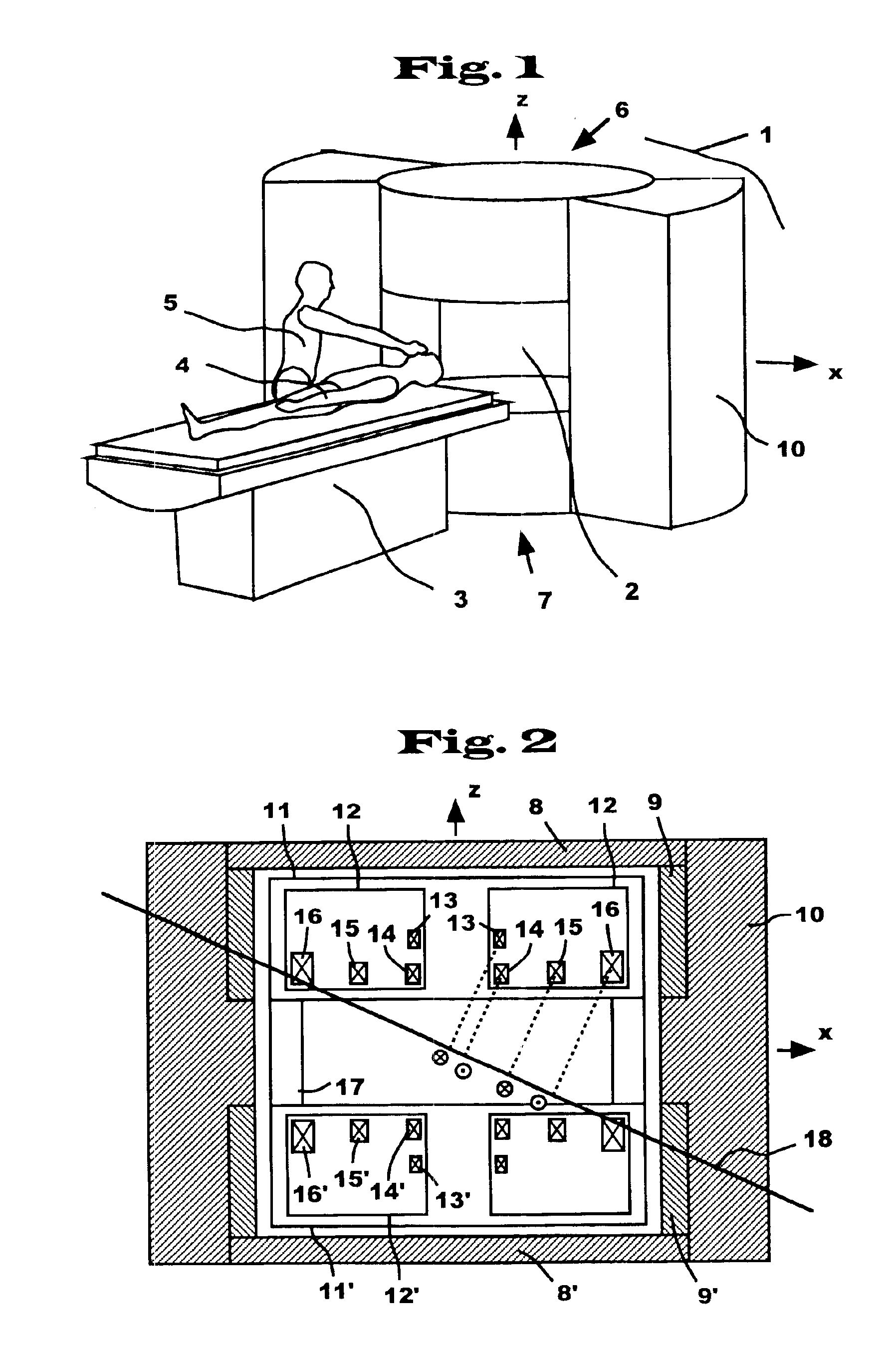
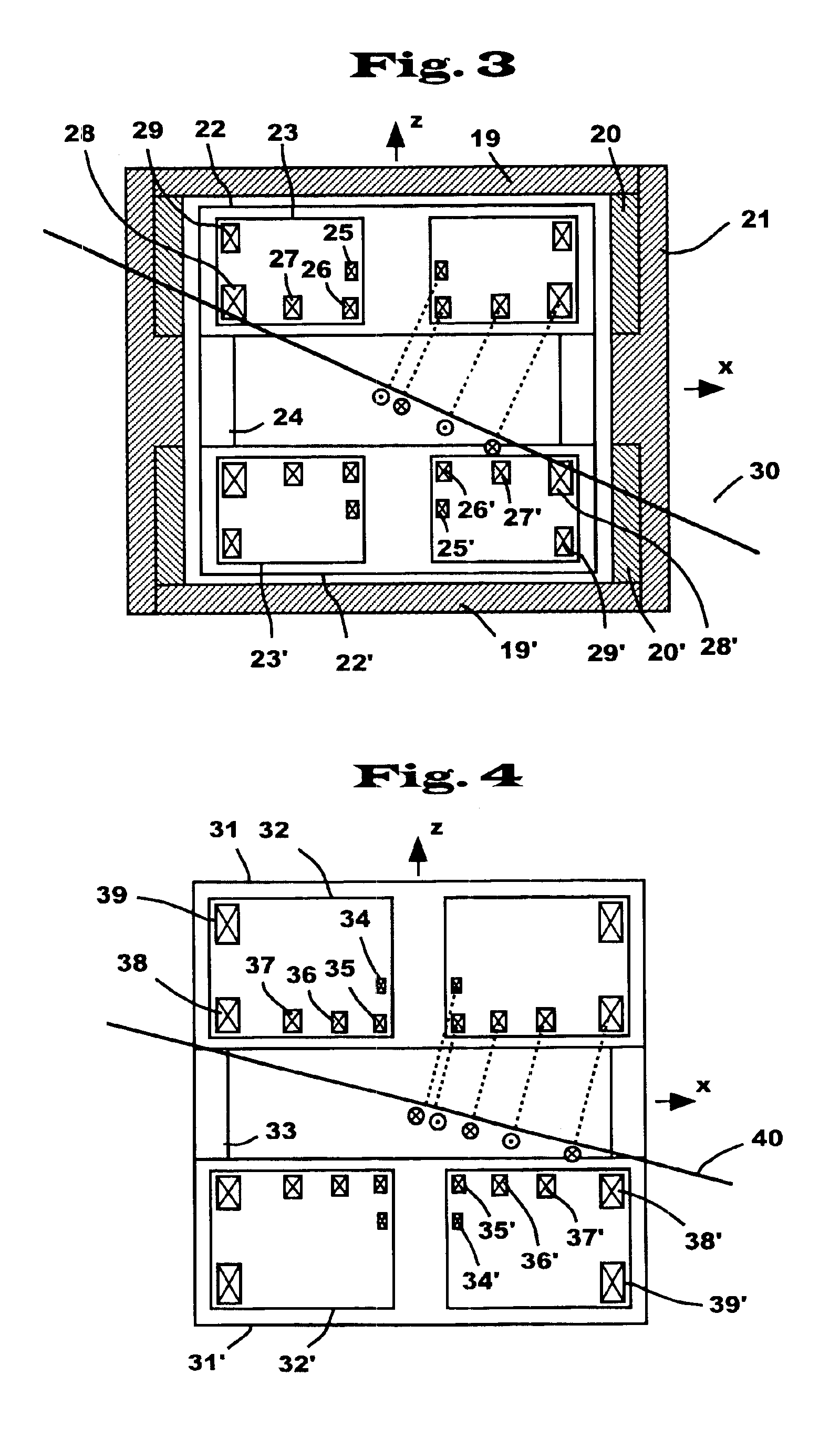
Hereinbelow, embodiments of the present invention will be explained specifically with reference to FIG. 1 through FIG. 12.

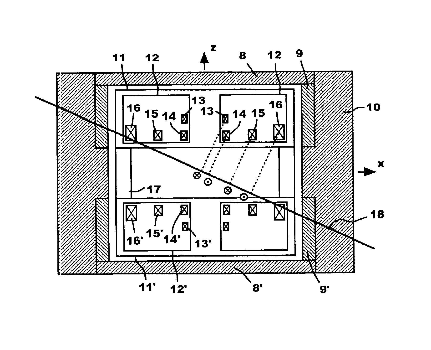
FIG. 1 is a perspective view of an open type super conducting MRI device using a super conducting magnet representing an embodiment according to the present invention. FIG. 2 is a cross sectional view on z-x plane of the super conducting magnet 1 among many constituting elements of the open type MRI device in FIG. 1.

The MRI device as shown in FIG. 1 produces a uniform magnetic field in z axis direction in an open region 2 by upper and lower super conduction magnet assemblies 6 and 7, and permits MRI image taking at the center portion of the open region 2. A patient 4 is carried by a bed and movable table 3 so that an image taking portion of the patient 4 positions at the center portion of the open region 2. The upper and lower super conducting magnetic assemblies 6 and 7 are magnetically coupled by column shaped external ferromagnetic bodies 10 and are further de...


PUM


Abstract

A magnet device includes two sets of static magnetic field generation sources spaced from each other in the vertical direction such that the uniform magnetic field region (patient space) is between then. Each set has concentric current carrying coils to generate a uniform magnetic field in a first direction (the vertical direction). Several such coils are used in each set, disposed such that when a first axis which is parallel to the first (vertical) direction and passes substantially through the centers of the current carrying coils crosses, at a first point, a second axis which is orthogonal to the first axis and is at substantially equal distance from the respective static magnetic field generation sources, the current carrying coils are disposed in such a manner that when geometrical centers of cross sections of the current carrying coils are projected on a first straight line that is in a first plane containing the first axis, the second axis and the first point and passing through the first point, the directions of the currents of the carrying coils at the respective corresponding projections align alternatively in positive and negative directions on the first straight line.

Description

FIELD OF THE INVENTIONThe present invention relates to a super conducting magnet which is suitable for a nuclear magnetic resonance imaging (hereinafter, simply called as MRI) device, and, more specifically, relates to a super conducting magnet device which is provided with a broad opening as well as makes easy to access to a measurement object by reducing the outer diameter of the magnet.BACKGROUND ARTConventionally, it was difficult that a person performing inspection such as a medical doctor accesses a person under inspection during image taking with an MRI device, therefore, the so called Interventional Radiology (hereinafter, simply called as IVR) was as well as difficult.For example, JP-A-7-106153 (1995) entitled “C Type Super Conducting Magnet” discloses a conventional art for avoiding the above problems.The above referred to device takes MRI images after inserting a patient between two magnetic poles.This device is for generating a uniform magnetic field by optimizing the co...

Claims


Application Information

Patent Timeline
IPC IPC(8): G01R33/38G01R33/381G01R33/3815
CPCG01R33/3806G01R33/3815G01R33/381
Inventor KAKUGAWA, SHIGERUKITAMURA, SHOUJIHARA, NOBUHIROKOMURA, AKIYOSHIHINO, NORIAKIKAWANO, HAJIMEHONMEI, TAKAOTAKESHIMA, HIROTAKAYATSUO, TAKESHITAZAKI, HIROSHI
Owner HITACHI MEDICAL CORP
Why Eureka
Try Eureka