Faraday rotator and optical device comprising the same, and antireflection film and optical device comprising the same

Inactive Publication Date: 2005-02-08
TDK CORPARATION
View PDF9 Cites 13 Cited by
  • Summary
  • Abstract
  • Description
  • Claims
  • Application Information

AI Technical Summary

Benefits of technology

[0028]One object of the present invention is to provide an optical device which is applicable to a small-s

Problems solved by technology

This brings about some problems in that the optical devices that comprise the Faraday rotator and the magnetic circuit for it are inevitably large-sized and their production costs increase.
Another problem with the Faraday rotator of the type is that, if the Faraday rotator is poorly heat-treated, it still has the growth-induced magnetic anisotropy remaining therein and, if so, its magnetic moment orientation does not move even when the direction of the external magnetic field H applied thereto is changed, and therefore the Faraday rotation angle does not change satisfactorily.
This is light loss through the Faraday rotator 1, and this increases the light loss in optical devices that comprise the Faraday rotator 1.
However, the Faraday rotator that has been heat-treated in the thus-controlled condition to satisfy the requirement will come up against a problem in that the Faraday rotation angle could not accurately vary within a desired range.
This problem after all lead

Method used


Image

  • Faraday rotator and optical device comprising the same, and antireflection film and optical device comprising the same
  • Faraday rotator and optical device comprising the same, and antireflection film and optical device comprising the same
  • Faraday rotator and optical device comprising the same, and antireflection film and optical device comprising the same

Examples


second embodiment

ew showing the outline of the Faraday rotator of the invention and an optical attenuator that comprises the rotator;

[0070]FIG. 16 is a view showing the condition of the antireflection film of the third embodiment of the invention, which is formed on both of the light-input / light-output surfaces of a magnetic garnet single-crystal substrate 31;

[0071]FIG. 17 is a view showing the condition of the antireflection film of Example 3-1 of the third embodiment of the invention, which is formed on both of the light-input / light-output surfaces of a magnetic garnet single-crystal substrate 31;

[0072]FIG. 18 is a graph showing the characteristics of the antireflection film of Example 3-1 of the third embodiment of the invention;

[0073]FIG. 19 is a graph showing the characteristics of the antireflection film of Example 3-2 of the third embodiment of the invention;

[0074]FIG. 20 is a graph showing the characteristics of the antireflection film of Example 3-3 of the third embodiment of the invention;...

example 1-1

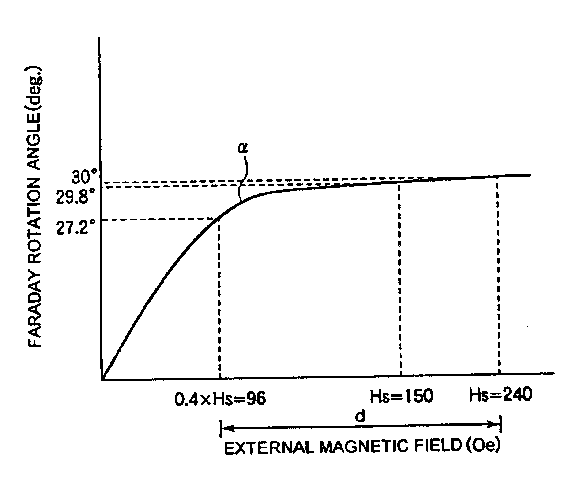
[0097]A magnetic garnet single-crystal film having a composition of Bi1.2Gd1.2Yb0.5Pb0.05Fe4.15Ga0.8Pt0.01Ge0.04O12 was grown in a mode of liquid-phase epitaxial growth, and worked into a magnetic garnet single-crystal plate. With varying its intensity, an external magnetic field H was applied to the thus-fabricated single-crystal plate substrate in the direction perpendicular to the substrate surface, and the Faraday rotation angle of the plate substrate was measured. The uppermost limit of the magnetic field H that did no more increase the Faraday rotation angle of the sample tested herein even though the intensity of the magnetic field H applied thereto was further increased is the saturation magnetic field Hs of the sample. To that effect, the intensity |Hs| of the saturation magnetic field Hs of this sample was measured at room temperature, and |Hs|=110 Oe.

[0098]The single-crystal substrate was heat-treated at 1100° C. for 30 hours, and its saturation magnetic field Hs was meas...

example 2-1

[0133]A magnetic garnet single-crystal film having a composition of Bi1.2Gd1.2Yb0.5Pb0.05Fe4.15Ga0.8Pt0.01Ge0.04O12 was grown in a mode of liquid-phase epitaxial growth, and worked into a magnetic garnet single-crystal plate. An external magnetic field H was applied to the thus-fabricated single-crystal plate substrate in the direction perpendicular to the single-crystal substrate surface, and the Faraday rotation angle F of the plate substrate was measured. The saturation magnetic field Hs of the sample was measured at room temperature, and it was 110 Oe. The saturation rotation angle Fs of the sample was measured with the saturation magnetic field Hs thereof being applied thereto, and it was 30 degrees. An external magnetic field H, 0.9 times the saturation magnetic field Hs, of 99 Oe was applied thereto, and the Faraday rotation angle F of the sample was measured, and was 28.2 degrees. The ratio of Faraday rotation angle F / saturation rotation angle Fs of the sample was 0.94.

[0134...


PUM


Abstract

The invention relates to an optical device for polarizing light by changing its Faraday rotation angle, such as optical attenuators, optical switches or polarization controllers; and its object is to provide such an optical device which can be driven even by small-sized and power-saving magnetic circuits and in which the insertion loss in the Faraday rotator may be reduced. The optical device comprises a Faraday rotator formed of a garnet single crystal, and a magnetic circuit applying an external magnetic field H that is smaller than the saturation magnetic field Hs of the Faraday rotator to the Faraday rotator.

Description

BACKGROUND OF THE INVENTION[0002]1. Field of the Invention[0003]The present invention relates to a Faraday rotator formed of a bismuth-substituted rare earth-iron-garnet single crystal and capable of reversibly controlling the plane of polarization through it, and relates to an optical device that comprises it (e.g., optical isolator, optical circulator, optical switch, optical attenuator, polarization controller).[0004]The invention also relates to an antireflection film formed on the surface of a Bi-substituted rare earth-iron-garnet material to be used for such a Faraday rotator, and to an optical device that comprises it.[0005]2. Description of the Related Art[0006]First Related Art:[0007]A Bi-substituted rare earth-iron-garnet film that has grown in a mode of liquid-phase epitaxial (LPE) growth has heretofore been much used for Faraday rotators for optical isolators in optical communication systems. Apart from their application to such optical isolators, in addition, Faraday ro...

Claims


Application Information

Patent Timeline
IPC IPC(8): G02F1/09G02F1/00G02F1/01
CPCG02F1/09G02F1/0036
Inventor OHIDO, ATSUSHITOHCHI, KENICHIYAMASAWA, KAZUHITOKAKEI, SHINICHIRO
Owner TDK CORPARATION
Why Eureka
Try Eureka