Distributed control system architecture and method for a material transport system

a control system and material transportation technology, applied in the direction of total factory control, furnaces, instruments, etc., can solve the problems of complicated material movement between conveyors and work stations along the path, carts and agvs lack the advantages of an automated conveyor, and semiconductor wafers are delica

Inactive Publication Date: 2005-02-08
MURATA MASCH LTD
View PDF6 Cites 80 Cited by
  • Summary
  • Abstract
  • Description
  • Claims
  • Application Information

AI Technical Summary

Problems solved by technology

Moving the material between the conveyor and work stations along the path can be complicated as care must be taken to ensure the transfer is accomplished without significantly interrupting the flow of material on the conveyor.
The cart and AGV lack the advantages associated with an automated conveyor, which can efficiently and rapidly move articles along a conveyor path and has much higher capacity than the cart and AGV.
Semiconductor wafers are delicate and, particularly in the later stages of processing, quite valuable.
With advances in technology, integrated circuits have become increasingly complex and typically include multiple layers of intricate wiring.
As a result of the increased complexity and decreased size of the integrated circuits, the value of the semiconductor wafer increases substantially as the wafer progresses through the various processing stages.
Also, the increased weight of a pod of 300 mm wafers creates ergonomic problems in manual wafer handling.
Thus, considerable care must be taken in handling the semiconductor wafers, particularly during the later processing stages, since damaged wafers could result in considerable monetary losses.
The number of sensors and motors that can be controlled by a PLC is limited.
One additional problem with this architecture is that the PLC must know the control interfaces of each of its associated devices.
Another problem is that a PLC is simultaneously concerned with high-level control issues, such as moving a pod to its destination without collisions, and low level issues, such as accelerating a motor.
Both problems are also a hindrance to transfer system scalability and reconfiguration.

Method used


Image

  • Distributed control system architecture and method for a material transport system
  • Distributed control system architecture and method for a material transport system
  • Distributed control system architecture and method for a material transport system

Examples


Embodiment Construction

The present invention is described herein with reference to a few specific embodiments. The present description uses terms whose meanings are provided in the following glossary:

A. Glossary of Terms

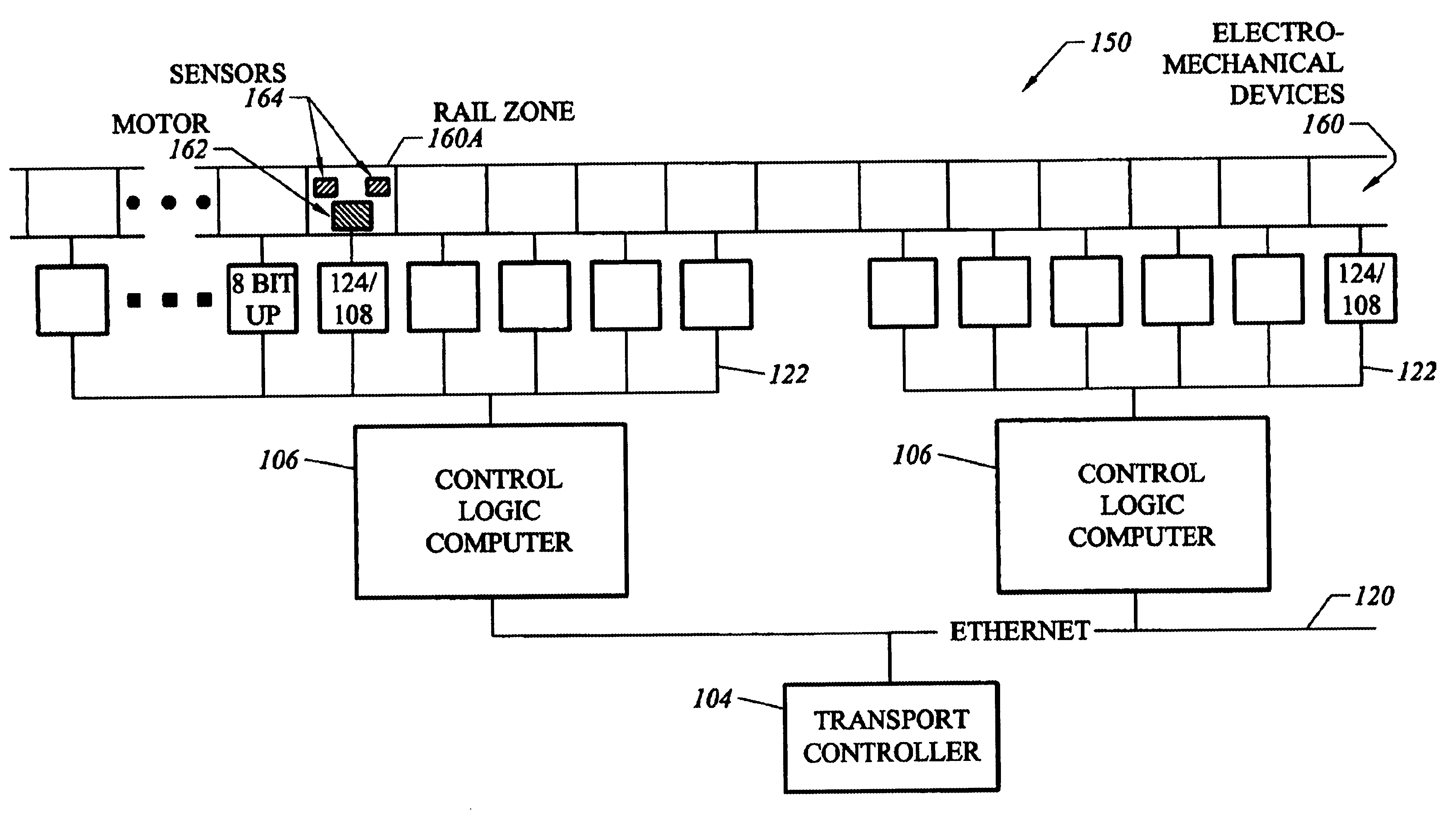
TermDefinitionAMHSAutomated Material Handling SystemCANController Area Network. Standard for networkingembedded devices together.CarrierSynonym for Container.CIMComputer Integrated Manufacturing. In this context theterm loosely means all computer systems with which theTransport System is in communication.ContainerGeneric term used to refer to an Open Cassette, Box orPod. A container is that object which is transported bythe Transport System.Control LogicHardware Platform for the mid-tier software components.ComputerCORBACommon Object Request Broker Architecture. Standarddeveloped by the Object Management Group (OMG) as amethod for distributed software applications to inter-operate over heterogeneous networks.CornerA corner is a director whose only function is to makecarriers turn a corner ...


PUM

PropertyMeasurementUnit
sizeaaaaaaaaaa
exit angleaaaaaaaaaa
speedsaaaaaaaaaa

Abstract

An automated transport system for use in a material handling system. The automated transport system employs a distributed control system including a top level controller (transport controller), a plurality of second-level controllers (control logic computers) and a plurality of third-level controllers (intelligent drivers). The transport controller (TC) receives material commands from a conventional material control system (MCS). The TC breaks the command into sub-commands directing selected control logic computers (CLCs) to acquire, move to a destination or otherwise interact with a particular container designated by the MCS command. The transport controller selects the CLCs based on the transport system topology, the content of the MCS command and knowledge of which regions of the transport system are controlled by respective CLCs. Each CLC implements the sub-commands by issuing to the intelligent drivers low level control commands to accelerate, elevate, rotate, load or unload the container. Each intelligent driver directly controls one of the electromechanical devices that compose the transport system hardware in accordance with these low level commands. The electromechanical devices can include rail sections (zones), directors, elevators, load port transfer devices and tag readers.

Description

The present invention relates generally to manufacturing control systems and, particularly, to control systems for use in material transport systems.BACKGROUND OF THE INVENTIONAutomated conveyor systems are used in a variety of applications to transport material. The material is typically loaded onto the conveyor using automated equipment which controls the flow of the material. Automated equipment is also used to remove the material at the exit point, with the conveyor and / or removal equipment being designed to allow several articles to accumulate near the contact point while preventing collisions between adjacent material units. With some applications, including semiconductor processing, the material must be temporarily moved from the conveyor to a work station at one or more locations along the conveyor path. The material is later returned to the conveyor, which then transports the material to the next work station or the exit point. Moving the material between the conveyor and w...

Claims


Application Information

Patent Timeline
Patent Type & Authority Patents(United States)
IPC IPC(8): B65G43/00B65G49/07B65G43/10B65G37/00C23C16/00C23C16/52C23C16/44C23C16/54G05B15/00G06F7/00H01L21/00H01L21/02H01L21/68H01L21/205H01L21/67B65GG05B19/418H01L21/677
CPCG05B19/4189G05B19/4182Y02P80/10Y02P90/02C23C16/00
Inventor WEHRUNG, BRIANHOLDEN, CLIFFORD
Owner MURATA MASCH LTD
Why Eureka
Try Eureka