System and method for real time reservoir management

a real-time reservoir and system technology, applied in seismology for waterlogging, borehole/well accessories, instruments, etc., can solve the problem of the relative high cost of most types of well intervention, and achieve the effect of maximizing the value of the ass

Inactive Publication Date: 2005-02-08
HALLIBURTON ENERGY SERVICES INC
View PDF47 Cites 120 Cited by
  • Summary
  • Abstract
  • Description
  • Claims
  • Application Information

AI Technical Summary

Benefits of technology

The present invention comprises a field wide management system for a petroleum reservoir on a real time basis. Such a field wide management system includes a suite of tools (computer programs) that seamlessly interface with each other to generate a field wide production and injection forecast. The resultant output of such a system is the real time control of downhole production and injection control devices such as chokes, valves and other flow control devices and real time control of surface production and injection control devices. Such a system and method of real time field wide reservoir management provides for better reservoir management, thereby maximizing the value of the asset to its owner.

Problems solved by technology

Unfortunately, not until the time at which the field was abandoned, and when the information is the least useful, did reservoir understanding reach its maximum.
Limited and relatively poor quality of reservoir data throughout the life of the reservoir, coupled with the relatively high cost of most types of well intervention, implies that reservoir management is as much an art as a science.
The reality, however, is that water expected to take three years to break through to a producing well might arrive in six months in one reservoir but might never appear in another.
Due to the complexity and time required to perform these functions, frequently an abbreviated incomplete analysis is performed with the output used to adjust a surface choke or recomplete a well for better reservoir performance without knowledge of how such adjustment will affect reservoir management as a whole.

Method used


Image

  • System and method for real time reservoir management
  • System and method for real time reservoir management
  • System and method for real time reservoir management

Examples


Embodiment Construction

Reference is now made to the Drawings wherein like reference characters denote like or similar parts throughout the Figures.

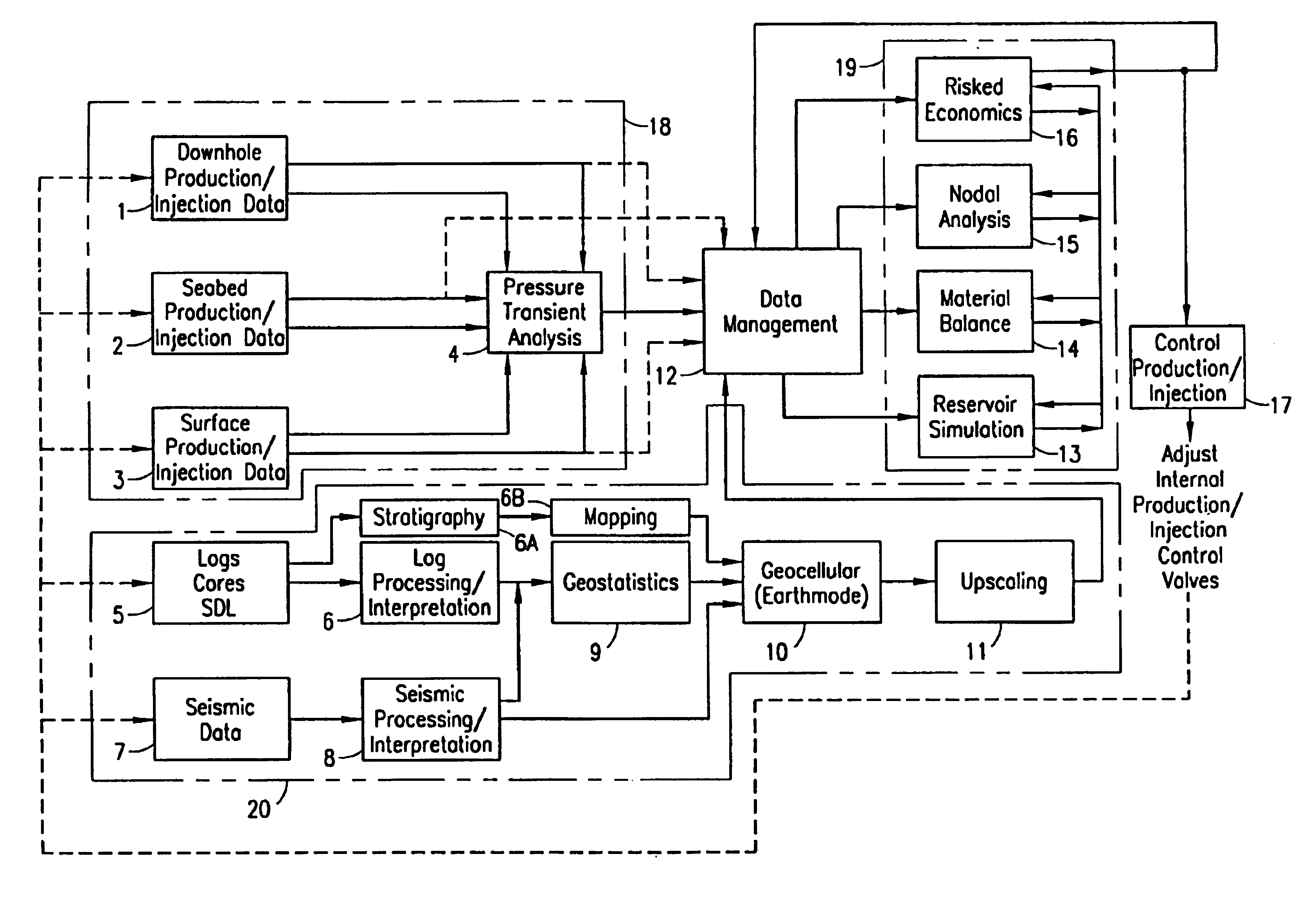
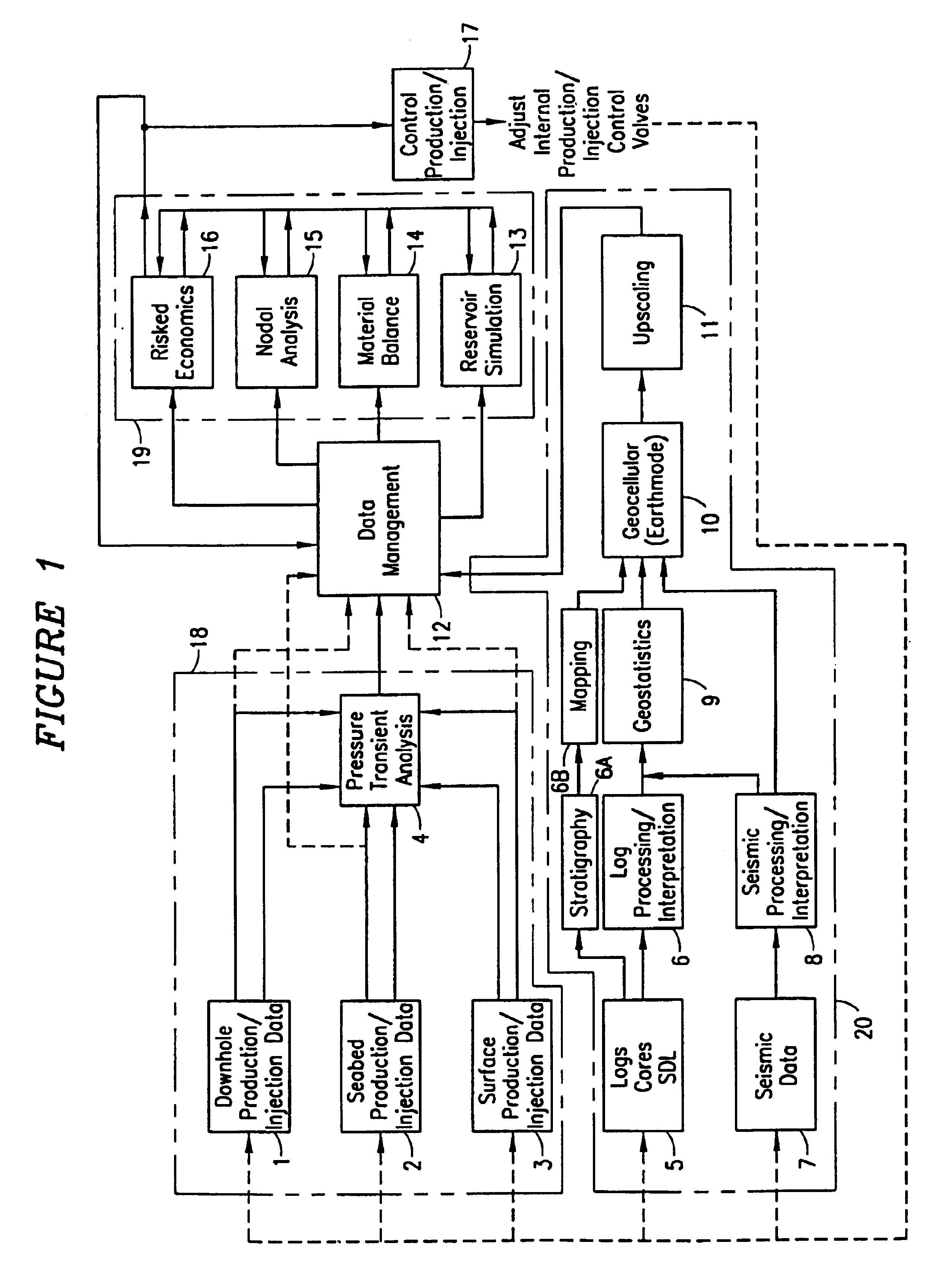
Referring now to FIGS. 1 and 4, the present invention comprises a method and system of real time field wide reservoir management. Such a system includes a suite of tools (computer programs of the type listed in Table 1) that seamlessly interface with each other in accordance with the method to generate a field wide production and injection forecast. It will be understood by those skilled in the art that the practice of the present invention is not limited to the use of the programs disclosed in Table 1. Programs listed in Table 1 are merely some of the programs presently available for practice of the invention.

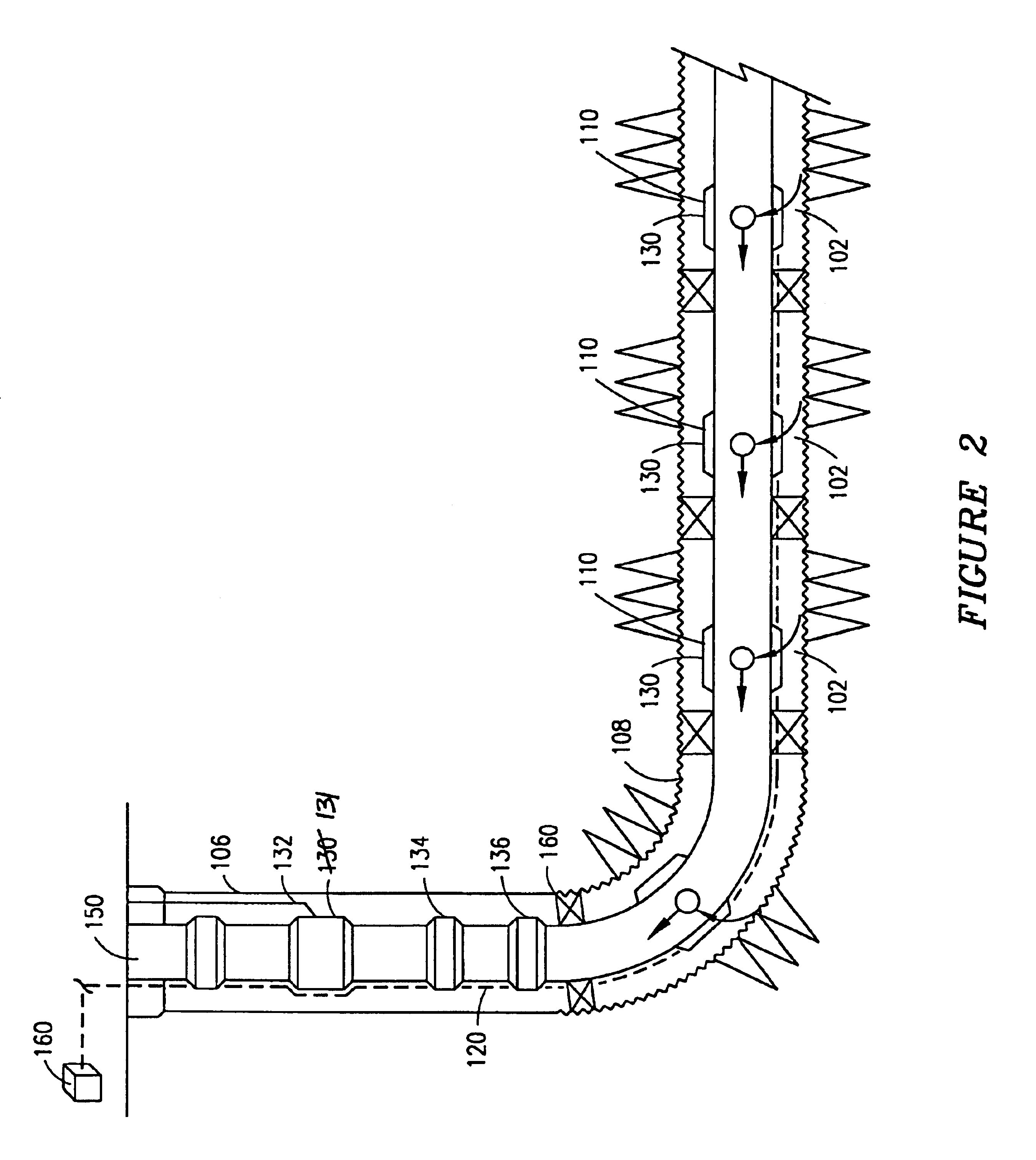
The resultant output of the system and method of field wide reservoir management is the real time control of downhole production and injection control devices such as chokes, valves, and other flow control devices (as illustrated in FIGS. 2 and 3 and othe...


PUM


Abstract

A method of real time field wide reservoir management comprising the steps of processing collected field wide reservoir data in accordance with one or more predetermined algorithms to obtain a resultant desired field wide production/injection forecast, generating a signal to one or more individual well control devices instructing the device to increase or decrease flow through the well control device, transmitting the signal to the individual well control device, opening or closing the well control device in response to the signal to increase or decrease the production for one or more selected wells on a real time basis. The system for field wide reservoir management comprising a CPU for processing collected field wide reservoir data, generating a resultant desired field wide production/injection forecast and calculating a target production rate for one or more wells and one or more down hole production/injection control devices.

Description

BACKGROUNDHistorically, most oil and gas reservoirs have been developed and managed under timetables and scenarios as follows:a preliminary investigation of an area was conducted using broad geological methods for collection and analysis of data such as seismic, gravimetric, and magnetic data, to determine regional geology and subsurface reservoir structure. In some instances, more detailed seismic mapping of a specific structure was conducted in an effort to reduce the high cost, and the high risk, of an exploration well. A test well was then drilled to penetrate the identified structure to confirm the presence of hydrocarbons, and to test productivity. In lower-cost onshore areas, development of a field would commence immediately by completing the test well as a production well. In higher cost or more hostile environments such as the North Sea, a period of appraisal would follow, leading to a decision as to whether or not to develop the project. In either case, based on inevitably...

Claims


Application Information

Patent Timeline
Patent Type & Authority Patents(United States)
IPC IPC(8): E21B43/00
CPCE21B43/20E21B43/14
Inventor THOMAS, JACOBGODFREY, CRAIG WILLIAMVIDRINE, WILLIAM LAUNEYWAUTERS, JERRY WAYNESEILER, DOUGLAS DONALD
Owner HALLIBURTON ENERGY SERVICES INC
Why Eureka
Try Eureka