Method of manufacturing a thin film magnetic head

a manufacturing method and technology of magnetic head, applied in the field of manufacturing a thin film magnetic head, can solve the problems of reducing the ion beam irradiation amount, increasing the width of the pole portion, and insufficient yield, etc., and achieves the effects of improving yield, high precision, and extremely minute pole width

Inactive Publication Date: 2005-02-15
TDK CORPARATION
View PDF5 Cites 10 Cited by
  • Summary
  • Abstract
  • Description
  • Claims
  • Application Information

AI Technical Summary

Problems solved by technology

However, there is a problem that yield (rate of conforming item) is not sufficient at the time of manufacturing the thin film magnetic head because it is conventionally difficult to make the pole width uniform with high precision for the following reason.
Because ion milling is conventionally used as an etching method on the bottom pole and the write gap, an etching process is not performed uniformly when a difference is made in an irradiation amount of ion beam on the etching region owing to the structure of the top pole and the like, so that the width of the pole portion is increased in a region where the irradiation amount of ion beam is reduced.
Such a problem is not resolved even though the etching process is performed while adjusting an irradiation angle of ion beam and / or rotating a substrate on which the pole portion and the like are formed.

Method used


Image

  • Method of manufacturing a thin film magnetic head
  • Method of manufacturing a thin film magnetic head
  • Method of manufacturing a thin film magnetic head

Examples


first embodiment

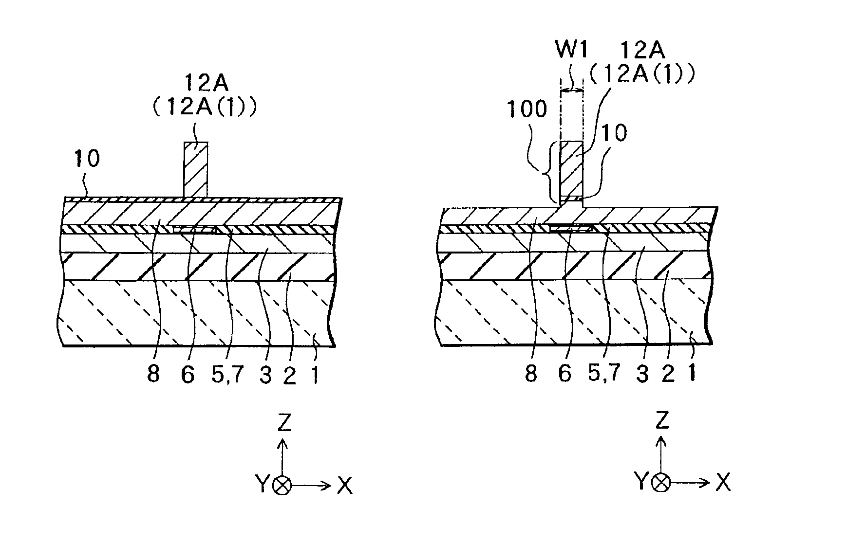
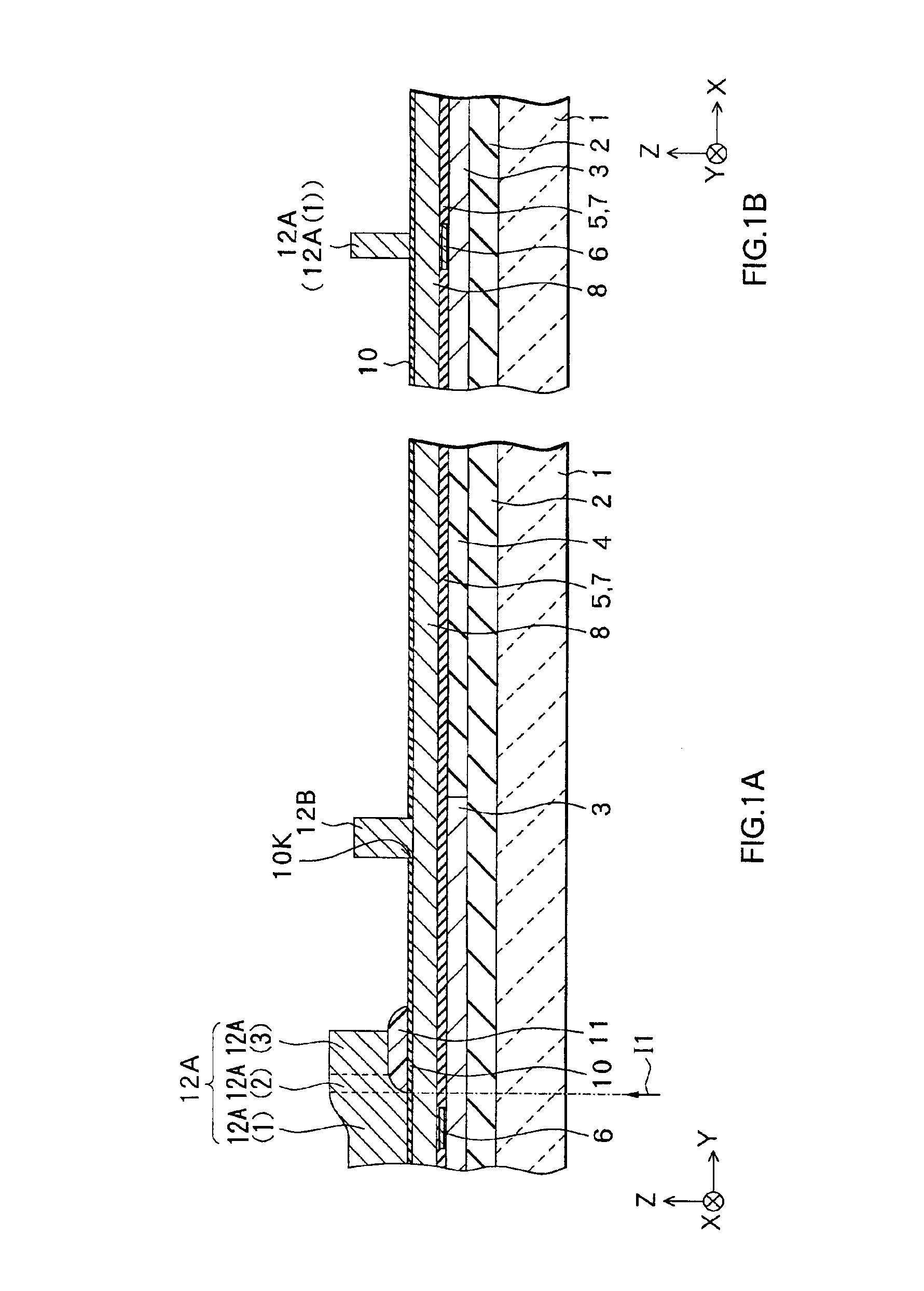
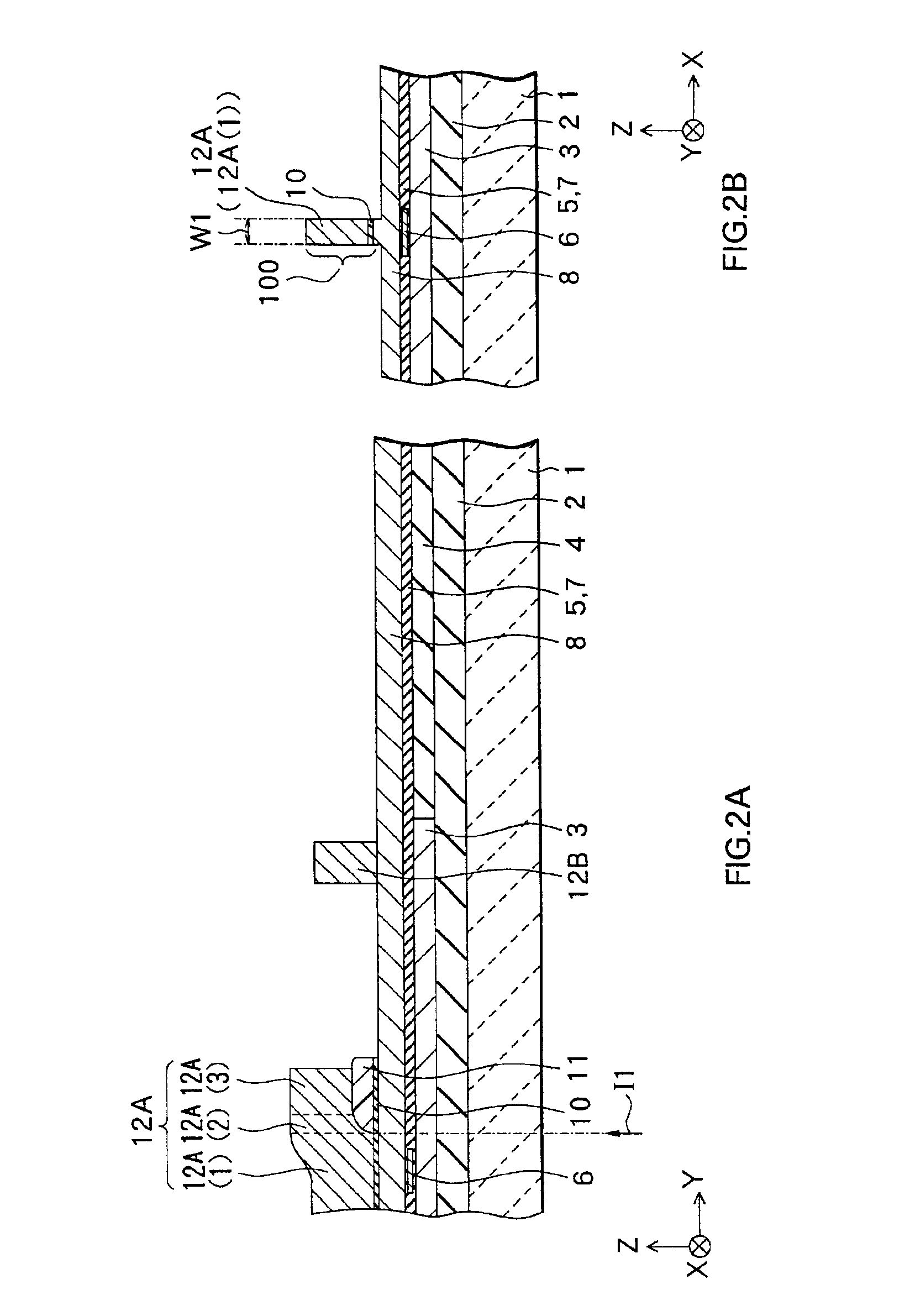
[0042]First of all, referring to FIGS. 1A and 1B to FIGS. 6A and 6B, and FIGS. 7 to 9, an example of a method of manufacturing a composite thin film magnetic head as a method of manufacturing a thin film magnetic head according to a first embodiment of the invention will be described.

[0043]In FIGS. 1A and 1B to FIGS. 6A and 6B, FIGS. 1A to 6A show cross sections each of which is perpendicular to the air bearing surface and FIGS. 1B to 6B show cross sections each of which is parallel to the air bearing surface of the pole portion. FIGS. 7 to 9 show perspective structures corresponding to main manufacturing processes. Here, FIG. 7 corresponds to a state shown in FIGS. 1A and 1B. FIG. 8 corresponds to a state shown in FIGS. 2A and 2B. FIG. 9 corresponds to a state shown in FIGS. 5A and 5B. However, insulating films 13, 15 and 17, thin film coils 14 and 16, an overcoat layer 18 and the like shown in FIGS. 6A and 5B are omitted in FIG. 9.

[0044]In the following description, the X axis dir...

second embodiment

[0097]Next, a second embodiment of the invention will be described.

[0098]First of all, referring to FIGS. 15A and 15B to FIGS. 19A and 19B, and FIGS. 20 to 22, a method of manufacturing a composite thin film magnetic head as a method of manufacturing a thin film magnetic head according to a second embodiment of the invention will be described. In FIGS. 15A and 15B to FIGS. 19A and 19B, FIGS. 15A to 19A show cross sections each of which is perpendicular to the air bearing surface and FIGS. 15B to 19B show cross sections each of which is parallel to the air bearing surface of the pole portion. FIGS. 20 to 22 are perspective views corresponding to main manufacturing processes. Here, FIG. 20 corresponds to a state shown in FIGS. 17A and 17B. FIG. 21 corresponds to a state shown in FIGS. 18A and 18B. FIG. 22 corresponds to a state shown in FIGS. 19A and 19B. However, in FIG. 22, insulating films 13, 15 and 17, thin film coils 14 and 16, an overcoat layer 18 and the like in FIGS. 19A and ...


PUM

PropertyMeasurementUnit
temperatureaaaaaaaaaa

Abstract

A method of manufacturing a thin film magnetic head capable of improving a yield while making a pole width extremely minute with high precision is provided. A write gap layer and a bottom pole are selectively etched in a region other than a portion corresponding to a front end part through the RIE with the front end part having an extremely minute uniform width as a mask in an atmosphere of gas including at least chlorine out of chlorine and boron trichloride and at an ambient temperature within a range of 30° C. to 300° C. The width (pole width) of a pole portion can be made uniform with high precision along a length direction so that the yield of the thin film magnetic head can be improved.

Description

BACKGROUND OF THE INVENTION[0002]1. Field of the Invention[0003]The present invention relates to a method of manufacturing a thin film magnetic head having at least an inductive magnetic transducer for writing.[0004]2. Description of the Related Art[0005]In recent years, an improvement in performance of a thin film magnetic head is demanded in accordance with an increase in surface recording density of a hard disk drive. As a thin film magnetic head, a composite thin film magnetic head in which a recording head having an inductive magnetic transducer for writing and a reproducing head having a magnetoresistive (hereinbelow, referred to as MR) element for reading are laminated is widely used.[0006]The recording head is, for example, constructed so as to include a top pole and a bottom pole sandwiching a write gap, and a coil for generating a magnetic flux disposed between the top pole and the bottom pole with an insulating layer in-between. The top pole and the bottom pole have unifo...

Claims


Application Information

Patent Timeline
Patent Type & Authority Patents(United States)
IPC IPC(8): G11B5/31G11B5/39
CPCG11B5/3116G11B5/313G11B5/3163Y10T29/49043Y10T29/49052Y10T29/49046Y10T29/49041G11B5/3967
Inventor SASAKI, YOSHITAKA
Owner TDK CORPARATION
Why Eureka
Try Eureka