Single-tube interlaced inductively coupling plasma source

a plasma source and inductive coupling technology, applied in the field of plasma formation, can solve the problems of multiple defects in the structure, worsening conditions, and increasing reaction ra

Inactive Publication Date: 2005-02-15
NOVELLUS SYSTEMS
View PDF6 Cites 30 Cited by
  • Summary
  • Abstract
  • Description
  • Claims
  • Application Information

AI Technical Summary

Problems solved by technology

In practice, it has been found that this structure has several defects.
Typically, one of the tubes receives more power through normal perturbations, and this conditi

Method used


Image

  • Single-tube interlaced inductively coupling plasma source
  • Single-tube interlaced inductively coupling plasma source
  • Single-tube interlaced inductively coupling plasma source

Examples


Embodiment Construction

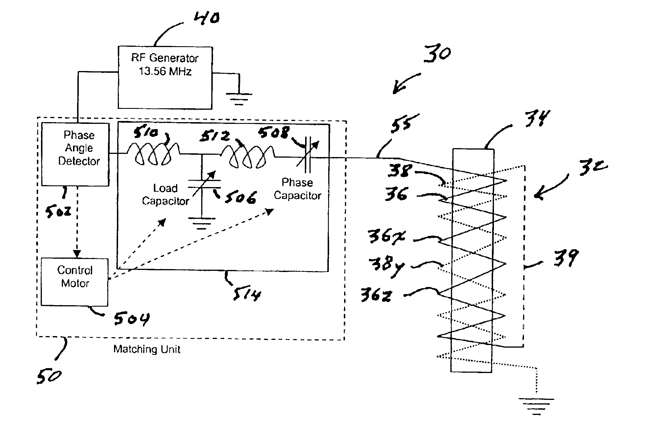
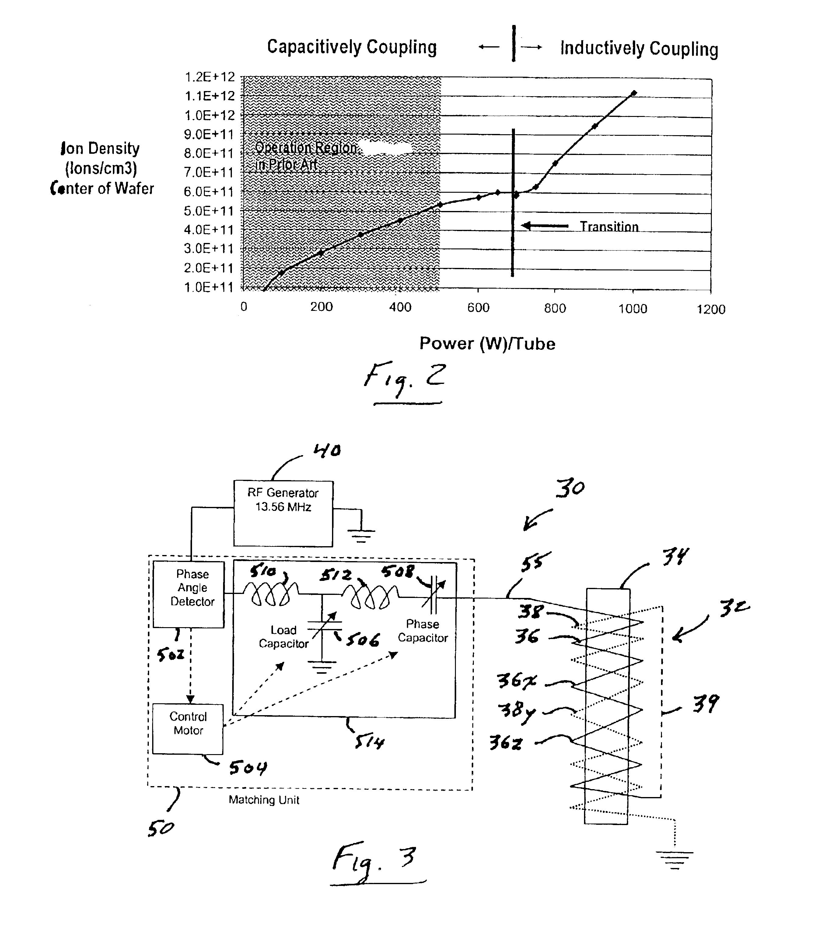
FIG. 3 is a schematic diagram of a plasma source 30 in accordance with this invention. Plasma source 30 includes a coil 32 which is wrapped around a tube 34.

Coil 32 is supplied by an RF generator 40, which operates at 13.56 MHz and which supplies a signal to coil 32 through an impedance-matching network 50. Impedance-matching network 50 includes a phase angle detector 502 and a control motor 504, which drives a load capacitor 506 and a phase capacitor 508 in an LC circuit 514. Circuit 514 also includes inductances 510 and 512, which are connected in series with phase capacitor 508. Matching network 50 is tuned to the impedance of coil 32 by minimizing the reflected power as seen by phase angle detector 502. The minimal reflected power is achieved through a tuning algorithm in which the positions of capacitors 506 and 508 are controlled by motor 504. To minimize the internal losses in matching network 50, capacitors 506 and 508 are preferably vacuum capacitors.

It should be understood...


PUM

PropertyMeasurementUnit
Lengthaaaaaaaaaa
Electrical inductanceaaaaaaaaaa
Phaseaaaaaaaaaa

Abstract

A plasma source for use in, for example, semiconductor processing contains a radio-frequency generator, an impedance matching network, and a coil that encloses a tube. The coil is bifilar, i.e., the turns of one are interlaced with the turns of a second winding. The matching network supplies only a single coil in the plasma source, unlike conventional arrangements wherein a single matching network supplies multiple coils in the plasma source.

Description

FIELD OF THE INVENTIONThis invention relates to the formation of plasmas for use in semiconductor processing and in particular to the formation of an inductively-coupled plasma.BACKGROUND OF THE INVENTIONPlasmas are widely used in the semiconductor industry for depositing thin films, for etching thin films and the underlying semiconductor material, and for dry-cleaning wafers. The plasma is typically formed in a cylindrical vessel or tube around which a wire is coiled. The reactant gases are introduced into one end of the tube and the atoms or ions that are generated by the plasma exit the other end of the tube and flow towards the wafer. Power is applied to the plasma by means of the coil. The mechanism by which the electrical power is transferred to the plasma can be either capacitive or inductive. Normally, both modes are present but one of the modes is predominant. In many applications the inductive mode is preferred because it produces a plasma having a higher ion density and b...

Claims


Application Information

Patent Timeline
IPC IPC(8): H01J37/32
CPCH01J37/32174H01J37/321
Inventor SU, YUH-JIACHEN, DAVID LEEDECAUX, VINCENT BERNARD
Owner NOVELLUS SYSTEMS
Why Eureka
Try Eureka