Coated phosphor filler and a method of forming the coated phosphor filler

a technology of coated phosphor and filler, which is applied in the field of coated phosphor filler and a method of coating phosphor filler, can solve the problems of unstable phosphor compound particles coated with inorganic film as phosphor filler, the reliability of such a prior art led is relatively low, and the individual phosphor compound particles tend to agglomera

Inactive Publication Date: 2005-02-15
DOCUMENT SECURITY SYST
View PDF18 Cites 7 Cited by
  • Summary
  • Abstract
  • Description
  • Claims
  • Application Information

AI Technical Summary

Benefits of technology

minates or at least reduces the disadvantageous effects of a thick inorganic coating film on unstable phosphor compound particles.
According to one aspect of the invention, there is provided a coated phosphor filler that includes a plurality of individual phosphor filler particles that are coated with a coating layer having a plastic substance, preferably an optically transparent epoxy composition.

Problems solved by technology

However, optical devices such as a light emitting diode (LED) including phosphor fillers according to the prior art, i.e. stable or unstable phosphor compound particles being coated with none or only one protective coating film, respectively, wherein the coating film consists of e.g. aluminium oxide, exhibit several shortcomings for the following reasons:(1) A significant basic problem of prior art LED devices of the type described above is that the phosphor filler, i.e. the individual phosphor compound particles tend to agglomerate.
Such an agglomeration leads, however, to a number of drawbacks in the operating characteristics of the LED device, such as uneven spectral and brightness distribution of the emitted light over the emitting surface of the device, loss of brightness of the LED device based on re-absorption effects between neighbouring agglomerated phosphor particles, etc.(2) The prior art LED devices containing unstable phosphor compound particles coated with an inorganic film as phosphor filler exhibits a relatively poor light extraction efficiency.
Consequently, the LED 200 is subjected to aging effects, so that the reliability of such a prior art LED is relatively low.
This effect is especially disadvantageous in applications such as traffic lights or signboards, which generally require lifetimes of the used optical device of more than 105 h.(4) If unstable phosphor compound particles are used in the drop 206 of the LED 200 which are individually coated with a protective coating film consisting of e.g. aluminium oxide, the protective coating reduces the optical transmission of the drop 206 and thereby the brightness of the LED 200.
Accordingly, the thickness of this protective coating and, consequently, the protection of the unstable phosphor compound particles are limited.
Accordingly, the performance of LED's using prior art phosphor filler is insufficient particularly with respect to the agglomeration problem, but, at least in case of unstable phosphor compound particles also with respect to light extraction, i.e. the brightness of the LED.
Accordingly, the reliability of the known LED devices is low.

Method used


Image

  • Coated phosphor filler and a method of forming the coated phosphor filler
  • Coated phosphor filler and a method of forming the coated phosphor filler
  • Coated phosphor filler and a method of forming the coated phosphor filler

Examples


Embodiment Construction

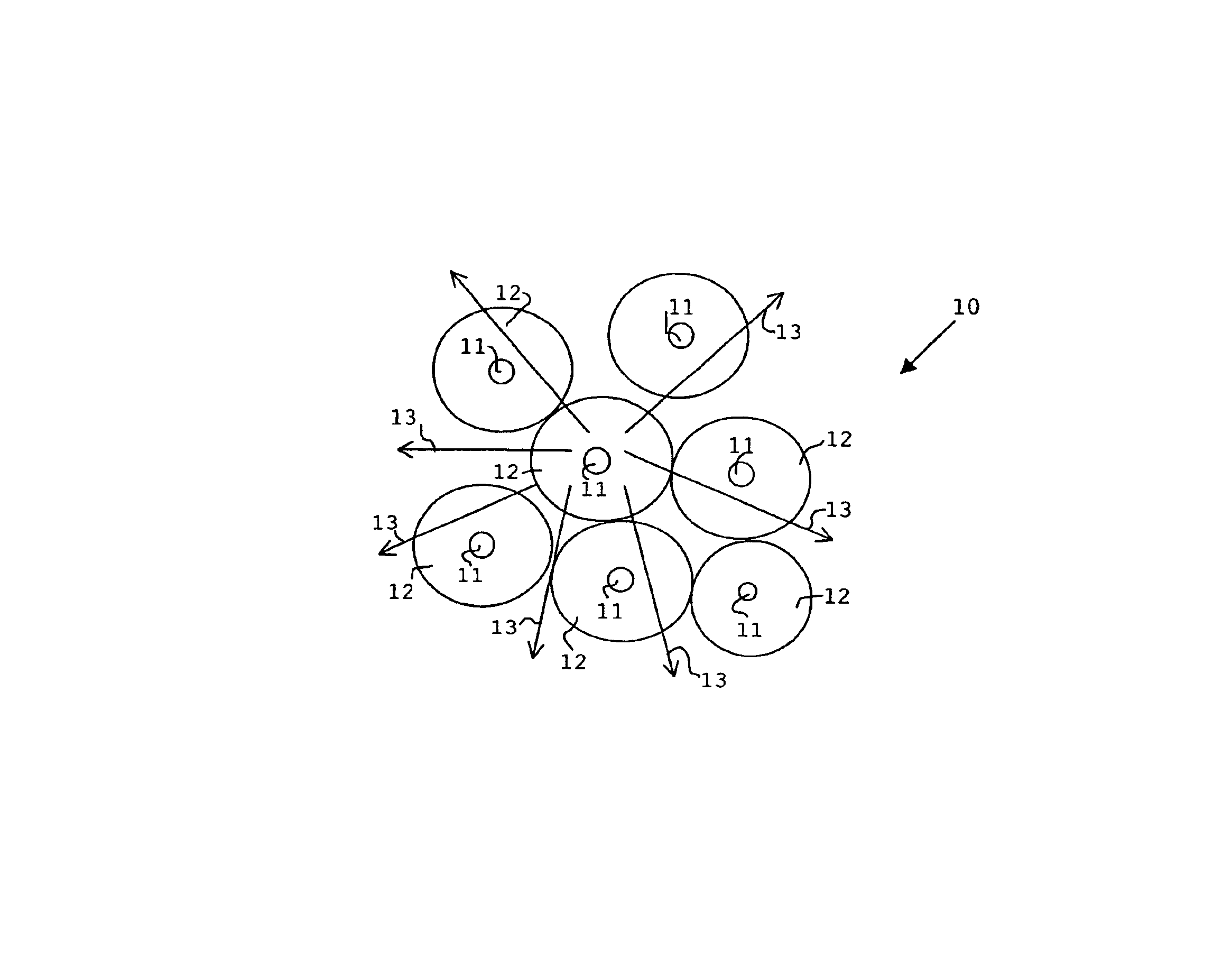
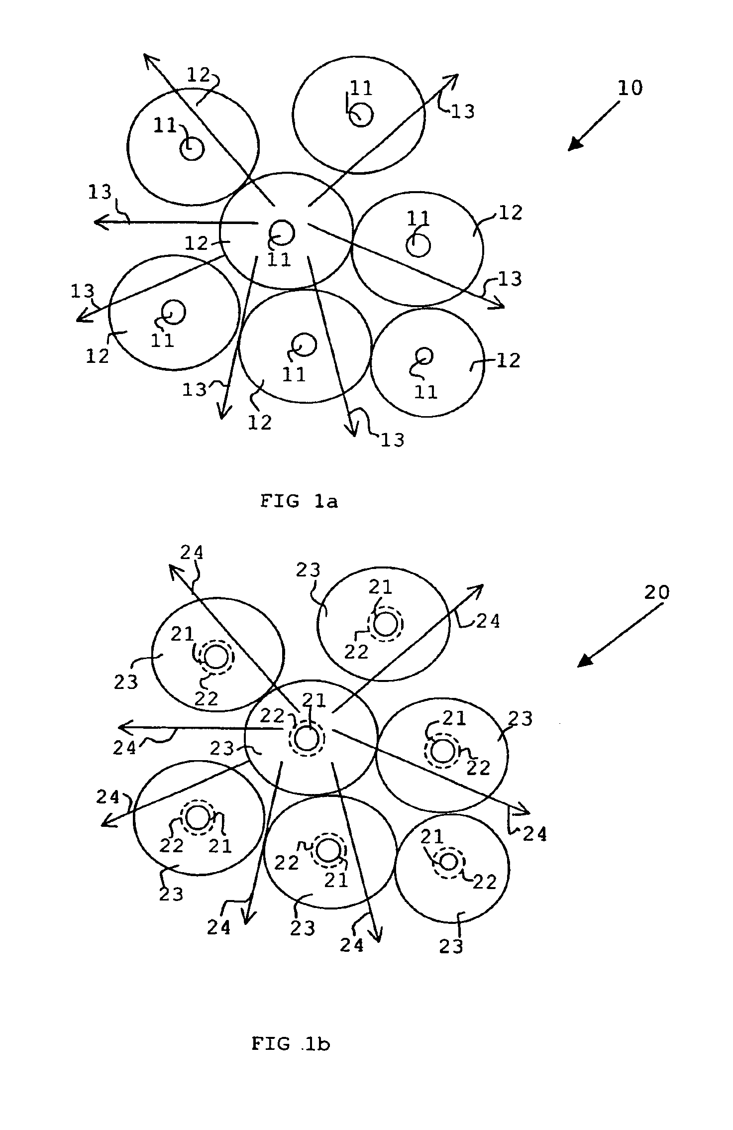
As will be described in more detail, a coated phosphor filler includes a plurality of individual phosphor filler particles that are coated with a coating layer having a plastic substance, preferably an optically transparent epoxy composition.

Due to this structure of the coated phosphor filler, the performance of an optical device, such as a LED, using such a coated phosphor filler is significantly improved with respect to light extraction, i.e. brightness of the LED device, and reliability of the LED device. Another advantage is that an enhanced reliability of the obtained LED is achieved due to a better passivation of the individual phosphor filler particles against elevated temperatures and humidity.

Since with regard to the optical transmissibility of the phosphor filler, the thickness of the coating layer made in accordance with one embodiment of the present invention is not critical, the distance between neighbouring phosphor filler particles may be significantly enhanced withou...


PUM

PropertyMeasurementUnit
thicknessaaaaaaaaaa
thicknessaaaaaaaaaa
thicknessaaaaaaaaaa

Abstract

An improved coated phosphor filler for an optical device includes a plurality of individual phosphor filler particles, and a coating layer having a plastic substance coated on each of the phosphor filler particles.

Description

The invention relates to a coated phosphor filler for an optical device (e.g., a light emitting diode (LED)), a method for forming a coated phosphor filler and a method for forming a LED making use of that coated phosphor filler.BACKGROUND OF THE INVENTIONIn the prior art, phosphor fillers including phosphor particles are used in a broad field of applications, ranging from electro-luminescence to photo-luminescence devices. This rich applicability is due to the favourable physical properties of phosphor such as a high luminescence efficiency and lifetime as well as due to the presence of suitable emission colours in the optical emission spectrum.A technological application of such phosphor fillers with increasing importance is the light emitting diode (LED), which comprises a LED-chip being electrically connected to a electrically conducting contact base. The LED-chip usually comprises a semiconducting p-n-junction, in which electrons and holes, which have been injected via a supply...

Claims


Application Information

Patent Timeline
Patent Type & Authority Patents(United States)
IPC IPC(8): C09K11/02C09K11/58C09K11/77H01L33/00C09K11/08C09K11/56C09K11/62C09K11/80H01L33/44H01L33/50H01L33/54H01L33/56H01L33/60H01L33/62
CPCC09K11/02C09K11/7731C09K11/7774C09K11/7786H01L33/501C09K11/584Y10T428/2995H01L2224/48091H01L2224/48247H01L2224/48257H01L2224/49107Y10T428/2993Y10T428/2998H01L2924/00014
Inventor CHUA, BEE YIN
Owner DOCUMENT SECURITY SYST
Why Eureka
Try Eureka