Eureka AIR delivers breakthrough ideas for toughest innovation challenges, trusted by R&D personnel around the world.

Cooling and counter-pressure method for producing plastic parts by injection

Inactive Publication Date: 2005-02-15
GRUPO ANTOLIN ING
View PDF5 Cites 0 Cited by
  • Summary
  • Abstract
  • Description
  • Claims
  • Application Information

AI Technical Summary

Benefits of technology

One object of this invention is to provide a cooling and counterpressure process for producing plastic parts by injection that manages to provide a suitable counterpressure that results in a high quality surface appearance of the parts, whether these are coated or non-coated.
Another object of the invention is to provide a cooling and counterpressure process for producing plastic parts by injection according to which a substantial reduction is achieved in the cooling and solidification, thus shortening the total cycle time and leading to units which are more economical to produce.
Another object of the invention is to provide a process that prevents any type of sinkholes and warpage in the parts to be produced.
Another object of the invention is to provide a process that practically does not alter the features of the coating on the parts, preventing them from being deteriorated.

Problems solved by technology

During the mould filling phase, if a coating is applied inside the cavity, the appearance of this coating deteriorates due to the high temperature of the material when it is injected and the high pressures which are created inside the cavity.
After this phase, the mould is cooled for a certain time, in a process in which this cooling time directly affects the productivity of the mould and, as a result, the final cost of the part to be produced.
With the application of this technique, an appropriate counterpressure is not achieved on the parts being produced, so that, in the case of coated parts, the coating is not suitably protected, whereas in the case of non-coated parts, unwanted sinkholes and warpage are not avoided.
Moreover, it has been found to be insufficient in practice, due to the relative slowness of the cooling process, which results in a cost of a certain consideration for each part produced.
In the same way, with this technique, a good surface quality in the finish of the parts is not achieved, whether coated or non-coated, and it has been found that in the case of coated parts, the coating has been substantially altered in relation to its initial appearance, which is the required finish.

Method used


Image

  • Cooling and counter-pressure method for producing plastic parts by injection
  • Cooling and counter-pressure method for producing plastic parts by injection
  • Cooling and counter-pressure method for producing plastic parts by injection

Examples


Embodiment Construction

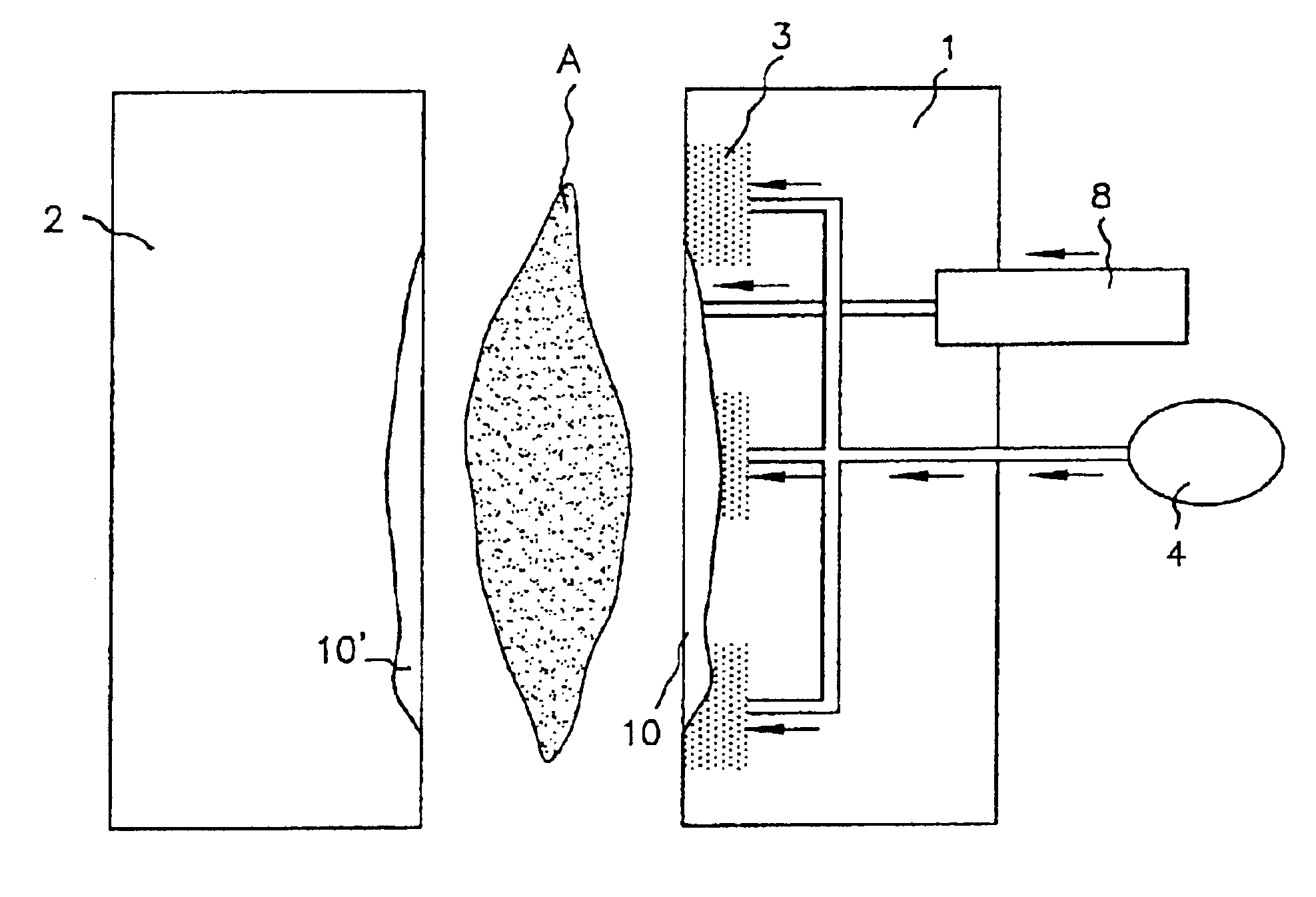
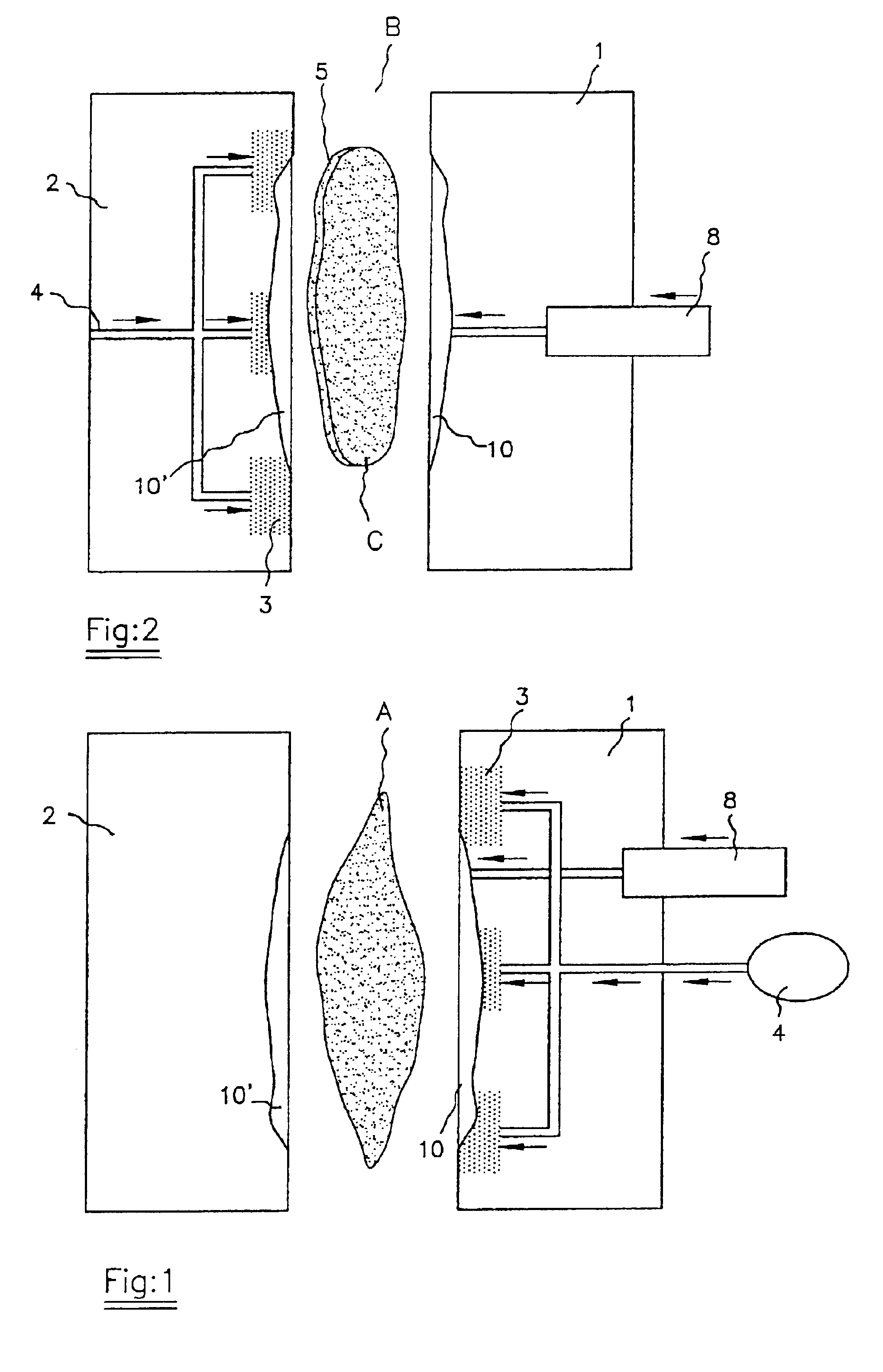
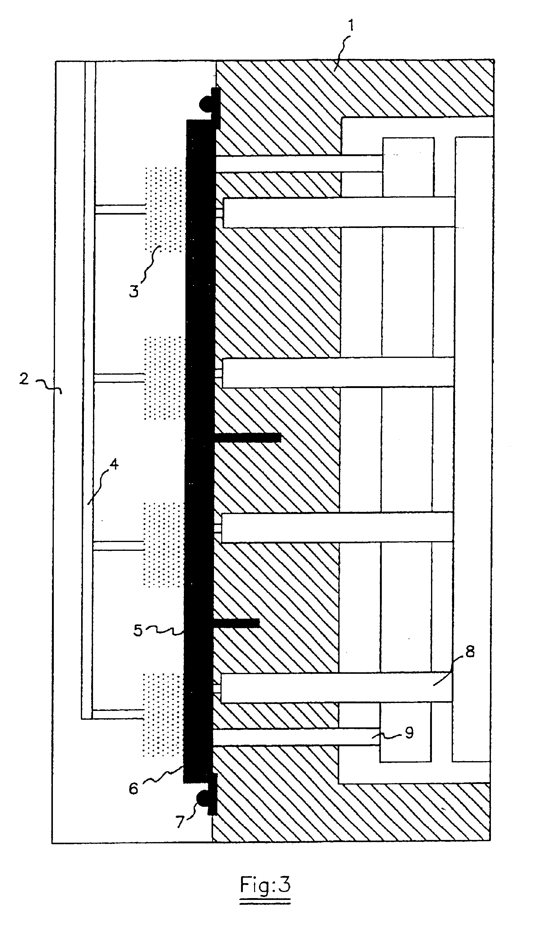
With regard to this FIG. 3, it is pointed out that the fixed part (1) and the mobile part (2) of the mould are shown. In the latter we can appreciate the distributed porous areas (3), which the gas arrives at through a general supply pipe (4).

Illustrated in the fixed part (1) of the mould are the system (8) for injecting the plastic material and the system (9) for ejecting or expelling the already finished part.

In the cavity we can observe the injected material (6) which has been infected at a process temperature between 180 and 320° C., the coating in question (5) and the perimetric gasket (7) around this cavity, which might be equipped with exhaust holes in order to remove the gas.

The porous areas (3) of the mobile part (2) of the mould are situated either well separated, as illustrated, or otherwise forming a single porous area in the said mobile part. The porous areas can also possibly be situated in the fixed part of the mould, as we shall see later.

In FIG. 1, we emphasis the f...


PUM

PropertyMeasurementUnit
Temperatureaaaaaaaaaa
Pressureaaaaaaaaaa

Abstract

A cooling procedure for the manufacture of plastic parts by injection, that uses a gas under pressure that is lodged in the cavity provided by the two mould parts (1, 2) during at least the cooling phase. The cold gas, and its application, covers both coated and non-coated part.

Description

BACKGROUND OF THE INVENTION1. Technical Field of the InventionThis inventions relates to a cooling and counterpressure or backpressure procedure for manufacturing plastic parts by the injection process, in which it is important to obtain a good appearance one of the sides of the part, the visible side, which might or might not be occupied by a decorative coating, which could be a plastic film, plastic foam, textile fabric, etc.2. Prior ArtOne of the most commonly used processes for obtaining plastic parts of this type, whether coated or not, is conventional plastic injection and, within this general technique, the variants that make it possible for the injection pressure, sequential injection and injection-compression processes to be lowered.These processes consist of the following phases:Placing the coating inside the mould, when dealing with a coated part.Total or partial closure of the mould (the latter in the injection-compression process).Injection of the material into the cavi...

Claims


Application Information

Patent Timeline
IPC IPC(8): B29C33/38B29C45/73B29C45/17B29C45/00B29C45/14B29C45/56B29C45/72
CPCB29C33/3814B29C45/1703B29C45/174B29C45/73B29C45/0053B29C45/14778B29L2031/3005B29C45/7207B29C2043/527B29C2045/7387B29C45/561B29C45/00
Inventor ANDRES, PABLO ESCRIBANO
Owner GRUPO ANTOLIN ING
Why Eureka
Eureka Blog
Learn More