Lamp filament design

a technology of lamp filaments and filaments, which is applied in the field of lamp filaments, can solve the problems of lamp failure, significant downtime for frequent replacement, and short lamp li

Inactive Publication Date: 2005-02-15
ASM IP HLDG BV
View PDF18 Cites 7 Cited by
  • Summary
  • Abstract
  • Description
  • Claims
  • Application Information

AI Technical Summary

Problems solved by technology

One problem with currently available radiant heating elements is that the lifespan of the lamps is short, causing significant downtime for frequent replacement.
Extended use of such lamps, typically including repeated cycling as wafers are sequentially loaded, processed at high temperature and unloaded, leads to lamp failure.

Method used


Image

  • Lamp filament design
  • Lamp filament design
  • Lamp filament design

Examples


Embodiment Construction

FIGS. 1-5 illustrate sections of lamps for purposes of describing problems and solutions with respect to filament support. FIGS. 6-8 illustrate lamps for purposes of describing problems and solutions with respect to filament expansion and contraction.

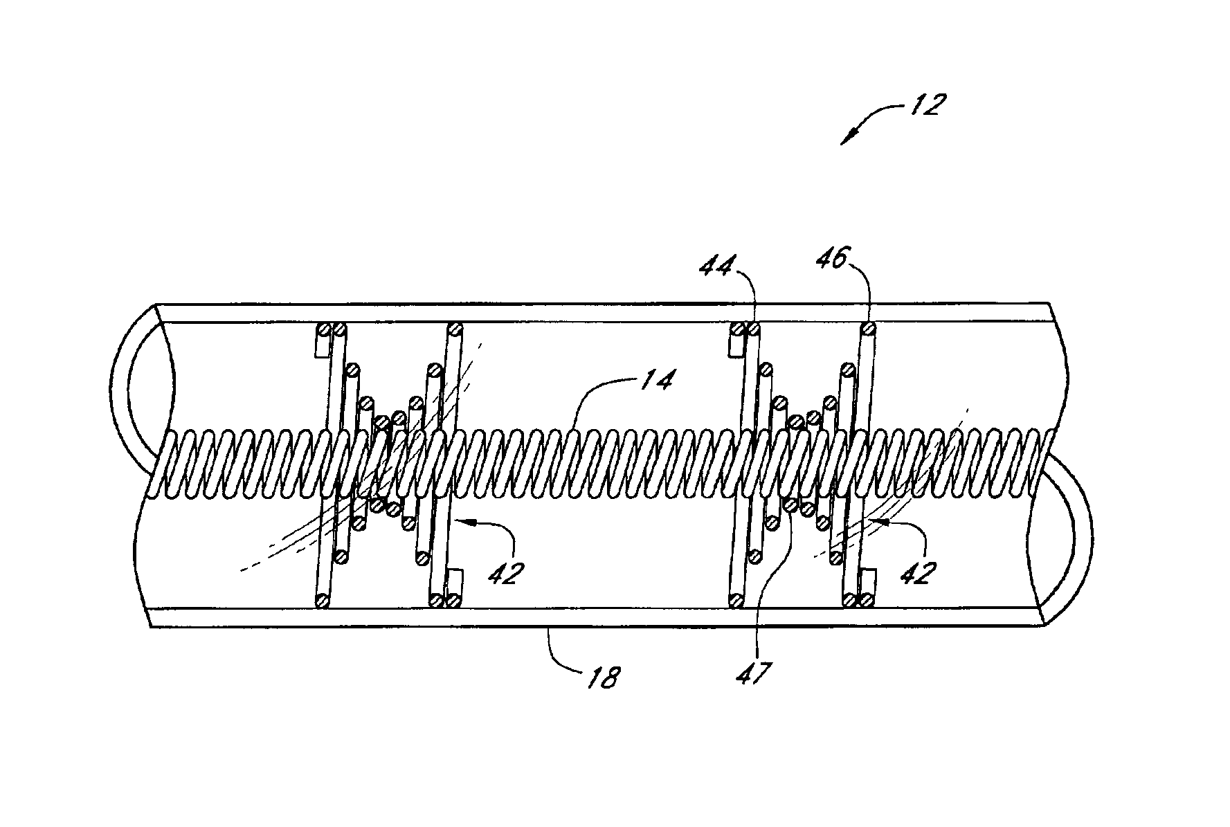
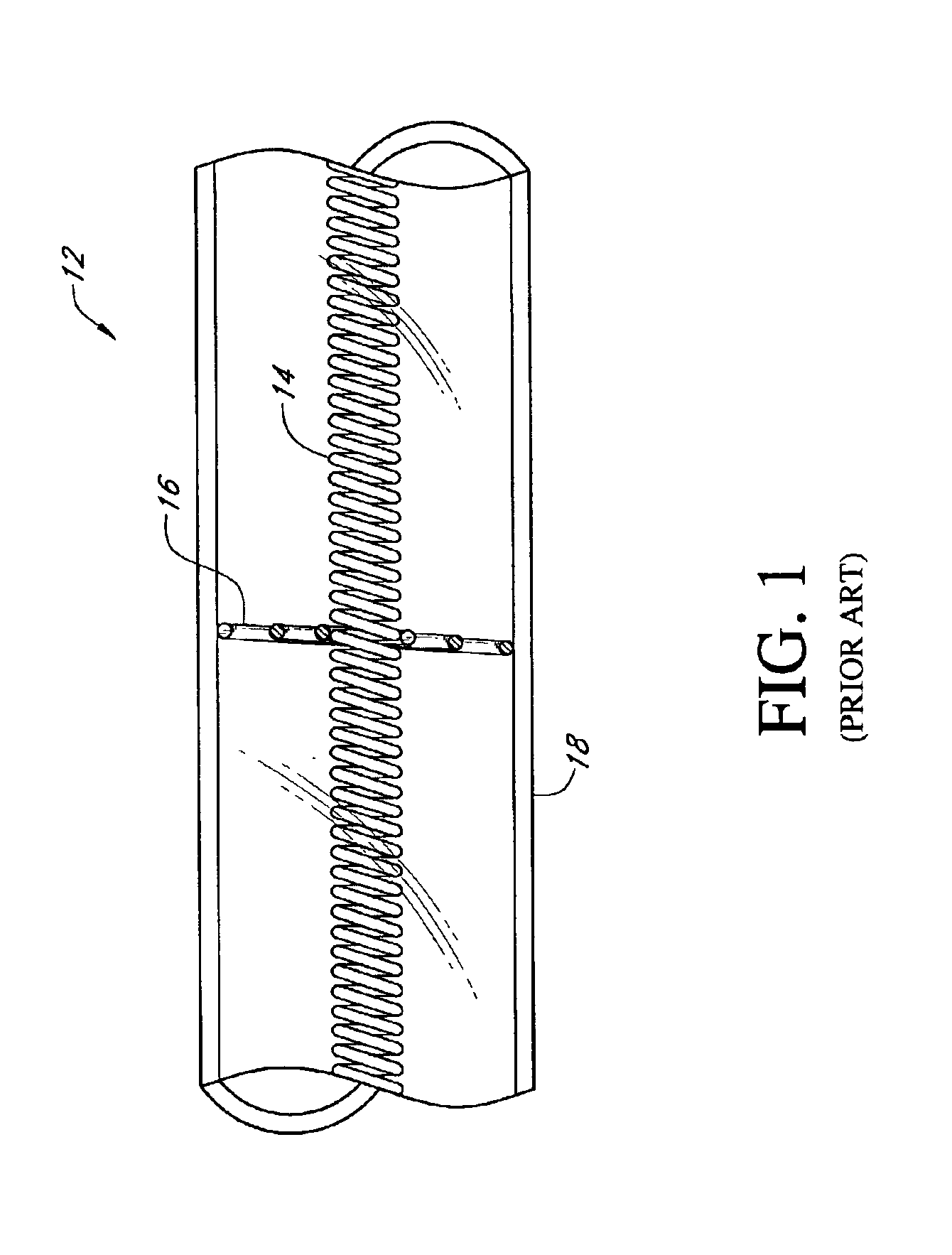
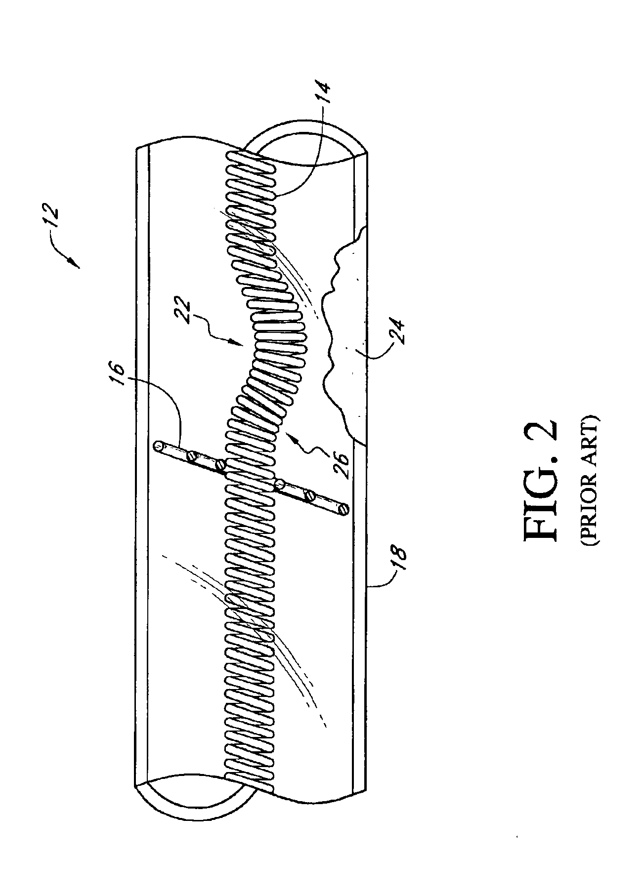
The material of a lamp filament used in radiant heating applications is typically tungsten wire, which does not maintain its stiffness at high temperatures. Conventionally, additional spiral support wires, each having a spiral or conical shape, are added around the filament periodically along the filament length to help support the filament, as shown in FIGS. 1-3.

FIG. 1 depicts a quartz lamp 12 as might be typically found in a reactor. The quartz lamp 12 comprises a filament 14, spiral filament support 16 and quartz sleeve 18. The support 16 contacts the filament 14 at an inner part of its spiral, and buttresses against the quartz sleeve 18 at an outer part of the spiral. Thus, the support 16 is intended to hold the filament 14 away fro...


PUM

PropertyMeasurementUnit
Temperatureaaaaaaaaaa

Abstract

An improved support is provided for locating a lamp filament axially within a lamp sleeve. The illustrated support is a spiral coil that includes a small diameter center portion that makes contact with the filament. On either side of the filament-contacting portion, the coil opens up to larger diameters for contacting the inner wall of the quartz sleeve within which the filament is housed. The support thus appears H-shaped when viewed from the side. A lamp filament is also provided with expansion compensation sections at either end of a central section. The filament wire in the compensation sections is wound into coils having a greater diameter and also a greater spacing between windings, as compared to coil in the central section. The expansion compensation sections are preferably capable of compressing and thereby absorbing thermal expansion of the filament during operation, without shorting the filament across adjacent windings.

Description

FIELD OF THE INVENTIONThe invention relates to lamp filaments generally and, more particularly, to improving support and design of filaments for high energy, radiantly heated semiconductor processing reactors.BACKGROUND OF THE INVENTIONChemical vapor deposition (CVD) is a very well known process in the semiconductor industry for forming thin films of materials on substrates and silicon wafers. In a CVD process, gaseous molecules of the material to be deposited are supplied to wafers to form a thin film of that material on wafers by chemical reaction. Such formed thin films may be polycrystalline, amorphous or epitaxial. Typically, CVD processes are conducted at elevated temperatures to accelerate a chemical reaction and to produce high quality films. Some processes, such as epitaxial silicon deposition, are conducted at extremely high temperatures (>900° C.).Substrates (e.g., silicon wafers) can be heated using resistance heating, induction heating or radiant heating. Among these...

Claims


Application Information

Patent Timeline
IPC IPC(8): A21B1/00H01J19/48H01J1/94H01J1/98H01K1/18H01J19/00H01K1/00H01J1/00H01J19/42H05B3/06F24C7/00H01K1/24H01K3/00H01K5/02H01L21/205H01L21/26H05B3/00H05B3/44
CPCC23C16/481H01K1/18H05B3/0047H01K3/00H01K5/02H01K1/24
Inventor HALPIN, MICHAEL W.
Owner ASM IP HLDG BV
Why Eureka
Try Eureka